Entenda por que o critério de perda de carga na entrada de 3% não é uma regra universal de aprovação/reprovação, o que controla sua aplicabilidade e como revisar uma instalação de válvula de segurança acima dele.

A Perda de pressão na entrada de 3% o critério é amplamente utilizado na análise de instalações de válvulas de alívio de pressão, mas não é uma regra universal de aprovação/reprovação para toda válvula de segurança, toda norma ou todo serviço.
Conforme a API 520 Parte II, o conhecido valor de 3% é um critério de triagem importante para perda de pressão não recuperável na entrada. As informações oficiais das normas da API identificam a Parte II, 7ª Edição, como a edição publicada utilizada para este artigo e observam que ela introduziu uma Análise de engenharia rota para avaliar instalações de dispositivos de alívio de pressão.
Essa distinção muda a forma como o número deve ser utilizado. O engenheiro não deve começar com a pergunta: “A queda de pressão está abaixo de 3%?” A sequência mais adequada é estabelecer a base normativa aplicável, confirmar qual perda está sendo calculada, identificar a válvula e a configuração de sensoriamento e, então, determinar se o critério conhecido é de fato o método de triagem aplicável.
Um resultado abaixo de 3% não garante, por si só, comportamento estável da válvula. Um resultado acima de 3% não prova, por si só, que toda instalação deva ser rejeitada. O que importa é a base de engenharia por trás do número.
O que o Critério de Perda na Entrada de 3% Significa — e o que Ele Não Prova
Conforme a API 520 Parte II, o critério conhecido refere-se à perda de pressão total não recuperável entre o equipamento protegido e a válvula de segurança, referenciada à pressão de ajuste da válvula.
A palavra não recuperável é importante. A perda de pressão na entrada não é simplesmente toda diferença de pressão que possa existir entre o equipamento protegido e a válvula. Atrito, turbulência, conexões, restrições e outras resistências ao escoamento podem dissipar pressão à medida que o fluido se desloca em direção à válvula. Efeitos de elevação e de velocidade recuperável devem ser tratados de acordo com o método hidráulico aplicável, em vez de serem agrupados indiscriminadamente em uma “queda de pressão de 3%”.”
A base de vazão também deve ser declarada. A capacidade nominal da válvula é uma base de projeto comum na prática da API, mas não é correto afirmar que todo cálculo de perda de carga na entrada, em toda configuração permitida, deve sempre usar a vazão nominal. Certos comportamentos da válvula e rotas de análise de engenharia podem alterar a base aplicável.
Por esse motivo, uma afirmação isolada como “perda de carga na entrada = 2,7%” é incompleta, a menos que a base de cálculo seja conhecida.
| Resultado do cálculo | O que ele estabelece | O que ele não estabelece |
|---|---|---|
| A instalação atende ao critério aplicável de triagem de perda de carga na entrada | Que esse critério hidráulico específico foi atendido | Operação estável garantida em todas as condições de alívio |
| A instalação excede o valor de triagem usual | É necessária análise técnica adicional | Batimento certo, falha automática ou rejeição universal por norma |
| Uma análise de engenharia permitida respalda a instalação | Pode haver uma base técnica documentada para a instalação específica | Que a capacidade, os limites específicos da válvula ou os requisitos do projeto podem ser ignorados |
Esta é a primeira grande correção à comum “regra dos 3%”: a porcentagem é um critério de triagem, não um limite físico de estabilidade.
As válvulas de alívio de pressão possuem dinâmica de sistema que uma única porcentagem não consegue descrever completamente. Atender ao critério de triagem, portanto, não deve ser interpretado como “a válvula não pode vibrar”, assim como ultrapassá-lo não deve ser interpretado como “a válvula vai vibrar”.”
O que controla se o critério dos 3% se aplica?
Antes de aplicar qualquer critério percentual, identifique a autoridade que realmente governa a instalação.
API, ASME, ISO, regulamentos nacionais, especificações do proprietário e instruções do fabricante podem influenciar um projeto, mas não têm escopo ou status idênticos.
Para um mapa mais amplo dessas funções, consulte o Guia de Normas para Válvulas de Segurança. da ZOBAI. Para projetos que utilizam especificamente a metodologia API, o guia de engenharia de válvulas de segurança API 520 fornece contexto mais amplo de dimensionamento e instalação.
Comece pela base normativa aplicável, não pela porcentagem
A ASME identifica o BPVC Seção VIII Divisão 1, 2025 como a edição vigente utilizada nesta análise.
Within the 2025 BPVC Section VIII Division 1 structure, the inlet-pressure-drop material relevant to this topic appears in Apêndice M não obrigatório, sob orientação de instalação e operação, com escopo explícito de dispositivo e serviço com fluido compressível. Esse status deve ser preservado, e não abreviado para “a ASME exige universalmente 3%”.”
A ISO apresenta uma ilustração diferente do mesmo problema. ISO 4126-9 é especificamente a parte de aplicação e instalação da família ISO 4126. Seu escopo publicado inclui válvulas de segurança e válvulas de segurança pilotadas e afirma que as informações de instalação pressupõem fluxo monofásico.
Portanto, “o projeto segue a ISO 4126” ainda não é informação suficiente. A parte relevante e o escopo de serviço importam.
Em seguida, identifique a configuração do dispositivo
A próxima questão é que tipo de dispositivo de alívio de pressão está instalado.
Uma válvula convencional de mola direta, um projeto balanceado e uma válvula de segurança pilotada não seguem necessariamente a mesma lógica de estabilidade ou de sensoriamento. Para um dispositivo pilotado, o local a partir do qual o piloto sensoreia a pressão do sistema protegido pode ser particularmente importante.
Isso não significa “pilotada = isenta da regra 3%”. A distinção correta é mais restrita: a specific sensing arrangement may change how inlet pressure loss affects valve control, while the main inlet hydraulics can still affect available relieving pressure and capacity.
Readers who need the operating distinction first can use the separate pilot-operated safety valve working-principle guide rather than expanding this article into a complete pilot-valve tutorial.
Confirm service and relief duty
The governing route can also depend on what the device is protecting against.
A narrowly defined liquid thermal-expansion duty should not automatically be generalized to process heating, vaporization, fire exposure, blocked outlet, or another credible overpressure scenario. Likewise, a single-phase installation basis should not be assumed to cover a two-phase relieving condition without checking the appropriate standard basis.
ISO makes that scope boundary clear: Part 9 states that its installation information assumes single-phase flow, while ISO 4126-10:2024 separately addresses safety-valve and bursting-disc sizing for gas/liquid two-phase flow.
The practical sequence is:
governing basis → device and sensing configuration → service and relief duty → calculation basis → applicable inlet-loss criterion.
The percentage comes after those questions.
Why Inlet Pressure Loss Can Affect Safety-Valve Stability
The reason inlet pressure loss matters becomes clearer once the valve starts flowing.
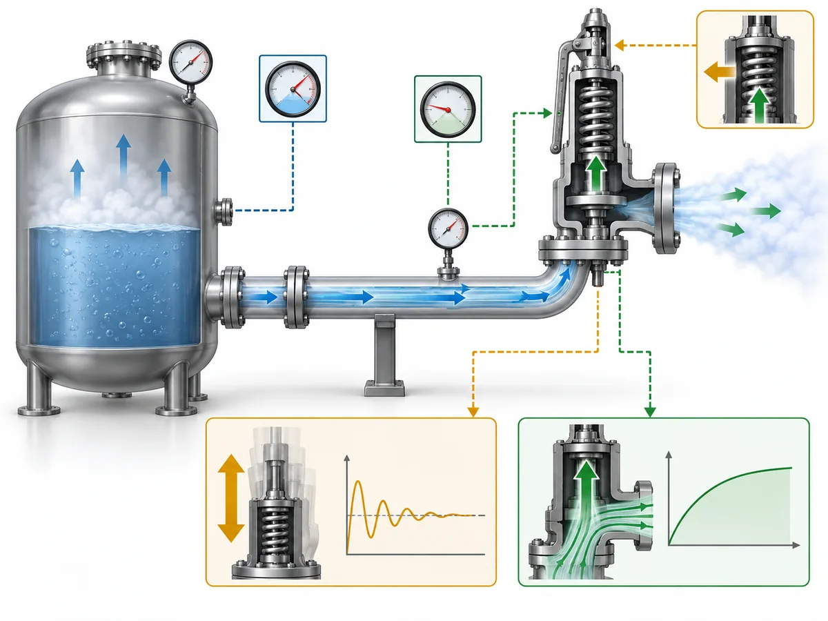
Before a relief event, the pressure at the protected system and the valve inlet may be relatively close, apart from relevant static effects. Once substantial relieving flow develops, friction and turbulence in the inlet path create nonrecoverable pressure loss.
The valve can then experience a lower inlet pressure than the protected equipment.
For a direct spring-loaded valve, that change can interact with the force balance that controls opening, lift, and reseating. A simplified sequence is:
protected-system pressure rises → valve opens → relieving flow increases → inlet losses increase → valve-inlet pressure changes → valve response changes → flow changes again.
Under unfavorable combinations of piping and valve behavior, this feedback can contribute to unstable operation.
It is still incorrect to convert that mechanism into “above 3%, the valve chatters.” Inlet pressure loss is only one part of the system. Valve characteristics, relief demand, outlet back pressure, sizing, and dynamic or acoustic interactions can also influence stability.
Outlet back pressure is a separate engineering variable from inlet pressure loss. Readers investigating the downstream side should use the dedicated Back Pressure in Spring Loaded Safety Valves guide instead of combining the two calculations.
Inlet loss also creates a second issue that should not disappear inside the chatter discussion: relieving capacity.
Nonrecoverable pressure loss reduces the pressure available at the relief-valve inlet during flow. Where that effect is material, the capacity consequence must be checked separately.
That gives the engineer two different questions:
Is the valve/system expected to operate stably?
Can the installed valve still deliver the required relieving capacity at the actual inlet conditions?
Passing one check does not automatically answer the other.
When the Familiar 3% Criterion Is Not the Whole Decision
“Not universal” does not mean “3% can be ignored.” It means recognized engineering frameworks contain scope-dependent cases where a simple comparison against the familiar screening value does not complete the decision.
A specific installation may require documented engineering analysis
API’s official information on API 520 Parte II, 7ª Edição confirms that the published edition introduced an Engineering Analysis for evaluating pressure-relieving-device installations.
Within API 520 Part II, that installation-specific route can extend beyond a single friction-loss percentage and, where applicable, consider capacity effects, valve behavior, force balance, system response, operating history, or dynamic interaction.
This should not be presented as an “exception that lets engineers ignore 3%.” The analysis exists to determine whether the specific installation has a defensible technical basis.
Known unstable behavior changes that decision. Under the API 520 Part II engineering-analysis framework used here, an existing installation with credible chatter evidence should not simply be reclassified as acceptable because a later calculation can be produced.
Narrow thermal-expansion service requires a narrow interpretation
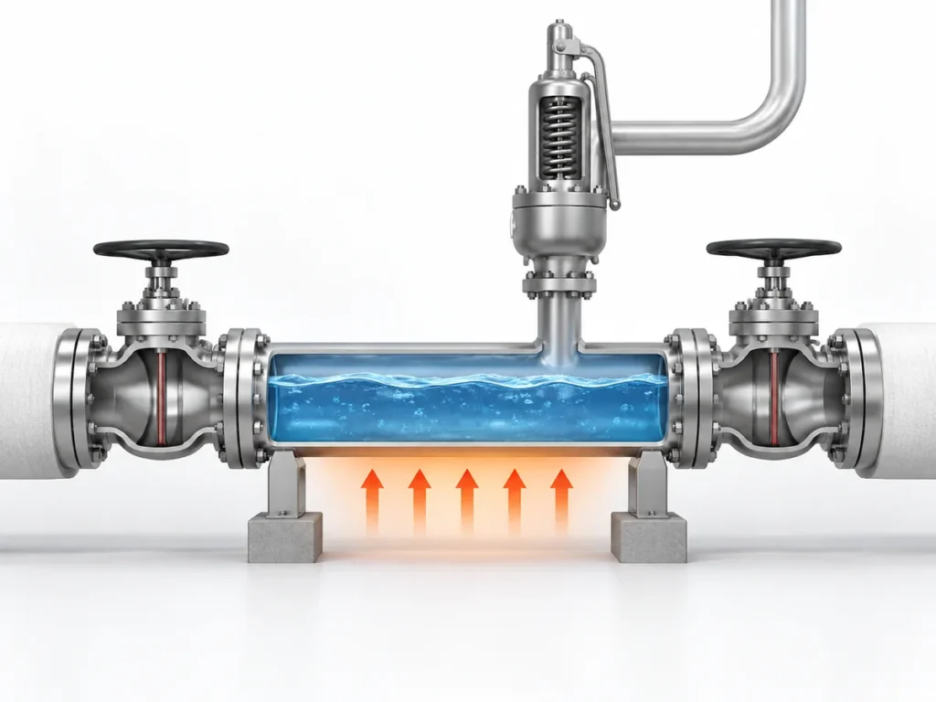
API 520 Part II also treats a narrowly bounded case involving liquid hydraulic expansion caused solely by ambient heating differently from the general inlet-loss screening path.
A palavra solely is critical.
The same treatment must not be silently expanded to every blocked-in liquid line, every thermal-relief valve, process heating that may vaporize the liquid, or a system with another credible overpressure scenario.
If the duty no longer fits that narrow basis, the ordinary inlet-loss assessment has to be revisited.
Remote sensing changes the question, not the laws of hydraulics
API 520 Part II gives specific treatment to a remotely sensed pilot-operated pressure relief valve. In that arrangement, the pilot can sense pressure at a location selected to represent protected-system pressure rather than relying only on the pressure at the main valve inlet.
That can alter the relationship between main-inlet pressure loss and pilot control.
It does não mean the pressure loss in the main inlet disappears. The main valve still has to pass the required relieving flow, so available inlet pressure and capacity remain relevant.
The sensing line itself also becomes part of the review. Its location, pressure losses, and compatibility with the chosen pilot design may require manufacturer-specific information.
Flow regime can change the standards basis
ISO 4126-9 states that its installation information assumes single-phase discharge, while ISO 4126-10:2024 deals with gas/liquid two-phase sizing.
That supports a scope boundary, not an invented second “two-phase 3% rule.”
If the relieving condition is two-phase, the correct action is to verify the applicable method—not to transfer a single-phase rule unchanged or invent an alternative percentage.
Across these examples, the engineering principle is consistent: do not search for an exception to 3%; identify the actual governing route for the device, duty, sensing arrangement, and installation.
How to Review an Installation Above the Familiar Criterion
An inlet-loss result above the familiar screening value is a reason to investigate. It is not enough information to approve or reject the installation.
1. Verify that the pressure-loss calculation is comparable with the criterion
Check the calculation boundary, inlet pipe geometry, fittings, reducers, restrictions, fluid properties, relief phase, and any upstream device that contributes hydraulic resistance.
A technically correct pressure-drop calculation can still be the wrong comparison if it uses a different pressure quantity or boundary from the governing criterion.
For broader installation geometry and piping considerations, see the Guia de Instalação de Válvulas de Segurança.
2. State the flow basis explicitly
Confirm whether the calculation uses rated capacity, required relieving flow, or another basis permitted for the actual device and assessment method.
Do not hide the assumption inside the hydraulic software or calculation sheet. It is one of the inputs that can materially change the reported loss.
3. Check relieving capacity separately
If inlet loss is significant, determine whether the installed inlet pressure changes the available relieving capacity.
If the real question is orifice and certified capacity rather than inlet piping alone, route that work to the Guia de dimensionamento e capacidade de alívio certificada de válvulas de segurança.
A stability assessment is not a substitute for this capacity check.
4. Confirm the valve architecture and sensing arrangement
Identify whether the device is conventional spring-loaded, balanced, pilot-operated, locally sensed, or remotely sensed.
Where an advanced assessment depends on opening, closing, or pilot characteristics, generic valve-type descriptions are not enough. Device-specific manufacturer information may be required.
5. Treat operating history as evidence—not proof of every future case
For an existing installation, useful records can include actual lift events, inspection findings, repair history, and evidence of damaged seats, guides, internals, or associated piping.
But “we have never seen chatter” is not the same as demonstrating that the system has successfully experienced the governing relief condition.
Conversely, credible evidence that the valve has chattered should materially change the decision. That condition deserves investigation and correction, not a paper justification based solely on a later calculation.
6. Determine whether a recognized engineering-analysis route applies
Where the governing framework permits it, a documented analysis can examine the actual installation rather than relying on the default screening value alone.
Depending on the method, that can require capacity correction, valve characteristics, force balance, pressure response, acoustic considerations, or operating evidence.
The purpose is not to find a mathematical way around the rule. It is to answer a narrower question: Can this particular device and installation be shown to satisfy the applicable engineering basis?
7. Change the installation when the evidence does not support it
Physical modification remains a valid—and sometimes necessary—outcome.
Depending on the cause, the engineering response may involve reducing inlet length, removing avoidable restrictions, using lower-resistance fittings, increasing inlet diameter, better matching the selected relieving capacity to the required load, changing the protection arrangement, or evaluating a different valve/sensing architecture.
Those are options, not a universal repair recipe.
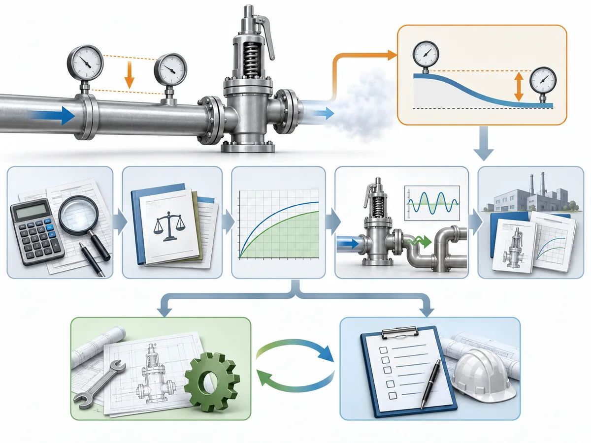
An exceedance should therefore lead to verify → classify → assess → redesign if necessary, rather than “3.1% → automatic failure” or “engineering analysis → automatic acceptance.”
What to Document for Engineering Review or RFQ
An engineer or valve supplier cannot evaluate an inlet-pressure-loss concern reliably from valve size and set pressure alone.
The review package should describe the protected system and the calculation that produced the concern.
| Informações a serem fornecidas | Why it affects the inlet-loss review |
|---|---|
| Protected equipment / pressure boundary | Defines where the inlet path begins |
| Governing code, standard, and project specification | Determines the applicable assessment basis |
| Cenário de alívio confiável | Defines the duty being reviewed |
| Base da pressão de ajuste | Required to interpret percentage-based criteria |
| Vazão de alívio necessária | Defines the required protection duty |
| Flow rate used in the inlet-loss calculation | Reveals whether the hydraulic basis matches the selected method |
| Fluid and relieving phase | Affects hydraulics and standards scope |
| Inlet piping layout / isometric | Shows line length, elevation, routing, and restrictions |
| Pipe sizes, reducers, fittings, and valves | Establish the sources of nonrecoverable loss |
| Rupture disk or other upstream device, if present | May add hydraulic resistance |
| Calculated inlet pressure loss and calculation method | Shows the result and how it was obtained |
| Relief-valve architecture | Affects the applicable stability or analysis route |
| Pilot sensing arrangement, where applicable | Can change how protected-system pressure is sensed |
| Device-specific operating data required by the selected analysis | Prevents generic assumptions about actual valve behavior |
| Lift, inspection, and repair history for an existing installation | May reveal evidence relevant to stability assessment |
This is also where general technical guidance ends and product-specific evidence begins.
A public article can explain the inlet-loss decision process. It cannot establish the dynamic behavior, remote-sensing arrangement, stability limit, allowable inlet pressure loss, or advanced-analysis data for a specific safety valve model unless those facts are documented for that model.
So a supplier inquiry should not stop at: “Can your valve work with more than 3% inlet pressure drop?”
A technically useful inquiry provides the relief duty, applicable standard, hydraulic calculation, valve configuration, and unresolved engineering question.