Una válvula de seguridad con camisa puede mantener el cuerpo de la válvula dentro de un rango de temperatura requerido, pero eso no significa automáticamente que la tubería de salida conectada esté bajo el mismo control térmico. La camisa protege únicamente la región física que realmente cubre. Una vez que el medio de proceso pasa más allá de esa región calentada, la trayectoria de descarga tiene su propia …


Una válvula de seguridad con camisa puede mantener el cuerpo de la válvula dentro de un rango de temperatura requerido, pero eso no significa automáticamente que la tubería de salida conectada esté bajo el mismo control térmico. La camisa protege únicamente la región física que realmente cubre. Una vez que el medio de proceso pasa más allá de esa región calentada, la trayectoria de descarga tiene su propia exposición a las condiciones ambientales, aislamiento, geometría de la tubería y cualquier trazado térmico de salida o sistema de trazado térmico de línea de descarga independiente.
Esa distinción solo importa cuando la temperatura puede cambiar de forma significativa el comportamiento del medio o la condición de la trayectoria de descarga. En algunos servicios, el enfriamiento puede aumentar la viscosidad, provocar congelación o solidificación, favorecer la cristalización o precipitación, o dejar material que no drena con facilidad. En otros servicios, el mismo grado de enfriamiento puede tener poco efecto práctico. Por eso el trazado de salida debe tratarse como una decisión de límite térmico específica del servicio, y no como un accesorio automático para toda válvula de seguridad con camisa.
La pregunta clave de ingeniería no es simplemente: “¿La válvula tiene camisa?”. Es:
¿Dónde debe terminar realmente el mantenimiento de temperatura para este medio, este escenario de alivio y esta configuración de descarga?
La válvula con camisa y la salida no comparten automáticamente el mismo límite térmico
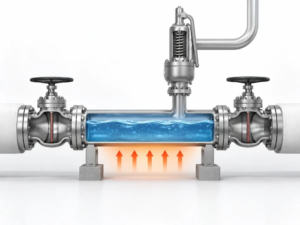
A válvula de seguridad con camisa normalmente se selecciona porque el control de temperatura alrededor de la válvula en sí es importante para el servicio. Según el diseño, la camisa puede cubrir el cuerpo de la válvula y extenderse alrededor de otras partes de la válvula, pero el límite calentado exacto es específico del producto y debe confirmarse con el plano o los datos del producto aplicables.
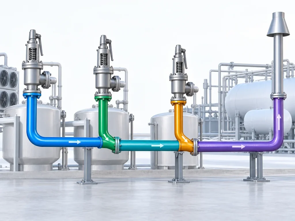
La tubería aguas abajo inicia un problema térmico diferente. Una vez que el medio pasa a una sección que ya no está calentada por la camisa, su temperatura se ve influida por el material y el diámetro de la tubería, la longitud expuesta, el aislamiento, las condiciones ambientales, los accesorios, las pérdidas de calor locales y cualquier trazado térmico independiente. Un tramo corto aislado dentro de un área de proceso cálida puede comportarse de forma muy diferente a una línea de descarga más larga expuesta a baja temperatura ambiente.
El final de la camisa de la válvula es un límite del producto. No es automáticamente el final del requisito de mantenimiento de temperatura para el proceso.
Una válvula con camisa no significa automáticamente que la salida deba estar trazada térmicamente. Si el medio descargado permanece aceptablemente fluido y estable en todas las condiciones aguas abajo relevantes, puede que no se requiera mantenimiento de temperatura adicional por esa razón térmica. La decisión de trazado térmico depende de lo que el cambio de temperatura realmente le hace al servicio.
Qué puede cambiar cuando la salida se enfría
El enfriamiento por sí solo no es el mecanismo de fallo. La cuestión importante es si el enfriamiento lleva el medio a un rango de temperatura en el que su comportamiento físico cambia lo suficiente como para afectar la trayectoria de descarga.
Para un líquido sensible a la temperatura, una temperatura más baja puede aumentar significativamente la viscosidad. En otro servicio, el enfriamiento puede cruzar un límite de congelación o solidificación. Otros medios pueden cristalizar, precipitar sólidos, condensarse o formar depósitos bajo combinaciones particulares de temperatura, composición y presión. Estos mecanismos no son intercambiables, y ninguno debe asumirse sin información específica del servicio.
El enfriamiento de la salida puede provenir de más fuentes que la pérdida de calor al ambiente
La exposición al ambiente es una fuente de enfriamiento de la salida, pero no es la única. En algunos servicios, la reducción de presión, el flashing o la expansión del gas a través de la trayectoria de alivio también pueden reducir la temperatura del fluido. Ese efecto de autorrefrigeración puede ser relevante donde el medio puede congelarse, formar hidratos, condensarse o depositar sólidos a la temperatura más baja.
Por esa razón, la temperatura de salida relevante debe provenir del caso real de alivio e invernaje, no solo de la temperatura normal del proceso aguas arriba. Si este mecanismo es relevante depende de la composición del fluido, el comportamiento de fases, el cambio de presión y la disposición de descarga.
La evaluación comienza con el medio: cambio de temperatura → respuesta del medio, no con la válvula.
Si el medio permanece totalmente fluido en el rango de temperatura esperado, una sección de salida sin calefacción puede no crear un problema térmico. Si, por el contrario, el enfriamiento hace que el material se vuelva muy viscoso, forme sólidos o se acumule en puntos bajos, la condición aguas abajo merece una revisión mucho más detallada.
Un cambio en el medio aún no equivale a una restricción
Incluso cuando el enfriamiento cambia la viscosidad o produce sólidos, eso no significa automáticamente que la línea de descarga se haya vuelto hidráulicamente restrictiva. La cantidad de material retenido, el área de flujo disponible, la geometría de la tubería, la tasa de alivio y las propiedades reales del fluido son relevantes.
Only when the resulting condition materially increases resistance through the discharge path does it become a pressure-loss issue.
A change in medium behavior does not by itself establish a back-pressure problem: outlet cooling ≠ built-up back pressure.
outlet cooling
→ may change medium behavior
→ may create accumulation or restriction
→ if the restriction materially increases pressure loss, built-up back pressure can increase
→ may change medium behavior
→ may create accumulation or restriction
→ if the restriction materially increases pressure loss, built-up back pressure can increase
In ISO 4126-7 terminology, built-up back pressure is the outlet pressure generated by flow through the safety valve and its discharge system. Whether an increase in that pressure materially changes safety-valve operation then depends on the valve configuration, the amount and variability of back pressure, manufacturer limits and the applicable relief-system design basis.
An untraced outlet should not be assumed to make a valve unstable or cause a particular performance problem. The hydraulic consequence has to be established separately.
The governing thermal condition may not be the full-flow relief event
Maximum relieving-flow temperature is not always the governing thermal condition.
Using the maximum relieving-flow temperature as the sole thermal basis may be appropriate in some systems, but it is not universal. A discharge line can experience different thermal states during startup, shutdown, standby, ambient exposure, smaller relief events and after a relief event when material remains in part of the piping.
A credible leakage, simmering or other small-flow case can also govern the thermal review. A small intermittent or continuous leak can enter an outlet that has cooled toward the winterizing temperature, and some project practices specifically check whether that leaking fluid would freeze, congeal or become excessively viscous under those conditions. This case should be evaluated where it is credible; it should not be assumed for every valve or service.
Consider a system that is normally hot but has long standby periods. The valve body may remain heated by its jacket while the connected outlet section approaches ambient temperature. If a temperature-sensitive fluid enters that cold section during a later event, the initial pipe condition can matter even though the flowing medium itself is hot.
In another service, continuous or repeated flow may keep the outlet sufficiently warm without separate tracing. The controlling condition has to be identified from the actual process rather than assumed from one operating point.
What Determines Whether the Outlet Actually Needs Tracing
The tracing decision becomes much clearer when it is treated as a set of engineering variables instead of a yes-or-no rule attached to the valve type.
| Factor de decisión | Por qué es importante | Qué se debe verificar |
|---|---|---|
| Comportamiento del medio | Determines whether cooling changes viscosity, phase, solubility or solids formation | Relevant temperature-property data and composition |
| Required temperature condition | Defines the temperature range needed to maintain acceptable flow behavior | Project or process maintain-temperature basis |
| Temperatura de alivio | Establishes the temperature entering the discharge path during the applicable relief case | Relief calculation / process data |
| Standby, startup and shutdown conditions | The coldest or most restrictive condition may occur outside normal operation | Estados de operación relevantes |
| Temperatura ambiente mínima | Afecta la pérdida de calor y la condición de arranque en frío | Datos de diseño de la instalación |
| Cobertura de la camisa | Define dónde se detiene realmente el calentamiento del lado de la válvula | Plano de la válvula o datos del producto |
| Geometría de salida | La longitud, el diámetro, los accesorios y la superficie expuesta afectan la pérdida de calor y el comportamiento hidráulico | Trazado real de la tubería |
| Aislamiento | Reduce la pérdida de calor pero no genera calor | Tipo, espesor y continuidad |
| Drenaje y puntos bajos | El material retenido puede experimentar un enfriamiento prolongado | Disposición de tuberías y drenajes |
| Destino de descarga | La presión del colector y las condiciones aguas abajo afectan el comportamiento global del sistema de alivio | Descarga abierta, sistema cerrado o datos del colector |
| Base de trazado térmico | Determina si el sistema propuesto puede mantener la temperatura requerida | Cálculo de pérdidas de calor y diseño del trazado |
| Requisitos del proyecto | Puede imponer requisitos adicionales de diseño o documentación | Especificación de proyecto aplicable |
Ningún elemento de esta tabla decide la cuestión por sí solo.
Por ejemplo, saber que un producto comienza a cristalizar por debajo de una determinada temperatura todavía no establece el diseño del trazado. El ingeniero también necesita saber si la sección de salida correspondiente puede alcanzar realmente esa temperatura, cuánto tiempo permanece en ella, si hay aislamiento, si queda material en la tubería y qué temperatura se espera que mantenga el sistema de trazado.
Del mismo modo, saber que la instalación tiene una temperatura ambiente mínima baja no demuestra que se requiera trazado. Si el medio no es sensible a esa temperatura o la sección correspondiente permanece suficientemente caliente por otras razones, la conclusión de diseño puede ser diferente.
Ruta de decisión de trazado en cuatro pasos
- Evaluar el fluido. Determinar si, dentro de un rango de temperatura creíble, puede volverse inaceptablemente viscoso, congelarse, solidificarse, cristalizar, condensarse, formar hidratos o crear de otro modo una restricción.
- Evaluar la temperatura de salida. Determinar si la salida puede realmente alcanzar ese rango durante el alivio, fugas o ebullición incipiente, espera, arranque, parada o condiciones posteriores al alivio, incluida la pérdida de calor ambiental y cualquier enfriamiento relevante por expansión o vaporización instantánea.
- Verificar la retención pasiva de calor. Determinar si la geometría real de la tubería, el calor residual del proceso y el aislamiento son suficientes para mantener la salida por encima de la base de temperatura de mantenimiento requerida sin trazado activo.
- Diseñar y verificar por separado. Si aún se requiere mantenimiento activo de temperatura, realizar el diseño de pérdida de calor y trazado, luego verificar por separado el drenaje, la hidráulica de salida, la contrapresión, los soportes y la descarga segura.
Utilizar esta secuencia para la evaluación y especificación. El cálculo de pérdida de calor del proyecto y el análisis hidráulico del sistema de alivio siguen siendo requisitos separados.
No existe una longitud de trazado universal
Una instrucción fija como “trazar el primer metro después de la válvula” no es una regla general fiable.
Required tracing coverage depends on the thermal duty. Pipe diameter, length, material, ambient temperature, insulation, fittings, equipment surfaces and the required maintain temperature all influence heat loss. A short uninsulated metallic outlet can present a different duty from a longer, well-insulated discharge line.
The maintain temperature also should not be chosen simply because the valve or upstream process operates at a particular temperature. The relevant target is the temperature needed to keep the medium within an acceptable condition for the actual service, while also respecting any product or material temperature limits.
Representative engineering scenario
Consider a jacketed safety valve protecting equipment that contains a temperature-sensitive liquid. The valve jacket maintains the valve region at the required process condition, but the outlet piping leaves the heated area and passes through a colder location.
The decision should not be reduced to: jacketed valve → trace the outlet.
A more reliable sequence is:
- Confirm where the valve jacket actually ends.
- Determine the temperature-sensitive behavior of the medium.
- Identify the relevant thermal condition during standby, startup, relieving and post-relief periods.
- Estimate or calculate the temperature condition of the outlet section.
- Determine whether that condition could create unacceptable viscosity, phase change or solids behavior.
- If temperature maintenance is needed, design the tracing and insulation for that thermal duty.
- Independently verify the outlet hydraulics, drainage and back-pressure conditions.
This sequence is illustrative, not a recorded customer case or a universal tracing specification.
What Outlet Tracing Cannot Fix
Outlet tracing can address a thermal problem. It cannot convert an otherwise unsuitable discharge system into an acceptable one.
If the discharge piping is undersized, unnecessarily restrictive or connected to a system with excessive downstream pressure, heat tracing does not correct the hydraulic design. If the piping traps liquid because of poor drainage or unsuitable low points, tracing does not eliminate the need to review the piping arrangement . It also does not establish that reaction forces, supports or safe discharge requirements have been addressed.
Different controls solve different problems
| Control | What it does | Qué no reemplaza |
|---|---|---|
| Heat tracing | Adds heat to maintain a required temperature condition where the thermal duty justifies it. | Does not correct undersized or overly restrictive discharge piping and does not by itself prove acceptable back pressure. |
| Aislamiento | Reduces heat loss and helps preserve available process or tracing heat. | Does not generate heat and does not correct retained liquid, poor drainage or an unsuitable piping layout. |
| Slope and drainage | Reduce the opportunity for liquid or residual material to remain in low points and cool for extended periods. | Do not maintain temperature and do not replace tracing where active heat input is actually required. |
| Outlet hydraulic design | Addresses piping size, layout, pressure loss and the resulting back-pressure condition for the relief system. | Does not keep a temperature-sensitive medium warm or prevent phase change and solids behavior by itself. |
The same boundary applies to safety-valve capacity. Adding heat tracing does not increase or prove the valve’s certified relieving capacity. Capacity remains dependent on the selected valve, orifice or flow area, service conditions and the applicable manufacturer or certification basis.
Contrapresión must also remain a separate check. If a temperature-related deposit reduces the effective flow path enough to increase pressure loss, built-up back pressure may rise. But the size of that effect cannot be inferred from the presence of deposits alone. It requires the actual relieving flow, outlet geometry, fluid properties and downstream pressure conditions.
Similarly, the resulting effect on the safety valve depends on the design being used. A conventional spring-loaded valve, a balanced bellows design and a pilot-operated valve do not have identical back-pressure behavior or limitations. Outlet tracing therefore should never be presented as a substitute for selecting and verifying the correct relief-device configuration.
What to Verify Before Specifying Outlet Tracing
A useful tracing specification should begin with service information rather than with a standard tracing temperature or a fixed length of pipe.
Before deciding the outlet treatment, confirm the following.
Medium and thermal behavior
Identify the medium, phase and composition closely enough to understand the temperature-dependent behavior that matters to the discharge path. Depending on the service, the relevant concern may be viscosity, freezing, solidification, crystallization, precipitation, condensation or another documented limitation.
Only properties that can change the tracing decision need to be established.
Relevant temperatures and operating states
Confirm the normal operating temperature and the relieving temperature, but also consider the conditions that may leave the outlet cold before a relief event. Minimum ambient temperature, startup, shutdown and standby conditions may be important where the process is intermittent.
A tracing design also needs a defined maintain-temperature basis. That temperature should come from the process requirement and validated medium behavior, not from a generic rule for jacketed valves.
Valve and piping boundary
Confirm the actual jacket coverage from the applicable product information. Then review the outlet diameter, length, material, fittings, insulation, exposed sections, low points, drainage and discharge destination.
This establishes where separate thermal control may be needed and provides the information required for a heat-loss or tracing design.
Relief-system conditions
Confirm the discharge arrangement and relevant back-pressure conditions independently of the tracing decision.
If the valve discharges into a closed header, existing superimposed back pressure and the additional built-up back pressure during relieving may both be relevant. If a thermal restriction is considered credible, its potential hydraulic consequence must be evaluated rather than assumed.
Tracing and insulation design
If the assessment shows that the outlet requires temperature maintenance, the tracing system should be designed for the actual thermal duty.
That normally means considering the required maintain temperature, minimum ambient condition, pipe geometry, insulation, heat loss, startup requirement and any equipment or fitting allowances. The choice between steam tracing and electric heat tracing should follow the project conditions and available utilities; neither method should be treated as universally preferable.
The final specification should also make the responsibility boundary clear. The valve manufacturer may need to confirm the jacket configuration and product temperature limits, while the process, piping or heat-tracing engineer may own the downstream thermal and piping design. Project responsibilities should be defined rather than assumed.
Pre-Specification Checklist
Before releasing the tracing requirement, verify that the project has enough information to answer these questions:
- What medium and phase can enter the discharge line?
- What temperature-dependent behavior creates the thermal concern?
- What is the relevant operating or relieving temperature?
- What are the important startup, shutdown or standby conditions?
- What minimum ambient condition applies?
- Where does the valve jacket actually end?
- What outlet piping remains outside that heated region?
- Is that piping insulated?
- Can material remain in low points or poorly drained sections?
- ¿Hacia dónde descarga la válvula?
- What back-pressure conditions apply?
- What temperature must the downstream piping actually maintain?
- Has the tracing duty been checked against the real pipe and insulation arrangement?
- Which requirements come from the process design, valve manufacturer and project specification?
If those questions cannot yet be answered, do not assign a tracing temperature or length. Close the missing engineering inputs first.
Safety and code boundary
API 520 Parte II addresses pressure-relief-device installation, while API 521 addresses pressure-relieving and depressuring systems, including disposal-system engineering. ISO 4126 provides additional safety-device terminology and technical framework. Those scopes are relevant to the wider relief-system review, but their names alone do not establish a universal requirement to heat-trace the outlet of every jacketed safety valve.
The applicable edition, project specification, process conditions and valve/manufacturer data still have to be confirmed.
Final design still requires the project relief calculation, piping review, manufacturer data and the applicable jurisdiction-specific code assessment.
Preguntas Frecuentes
Does every jacketed safety valve need outlet heat tracing?
No. A jacketed valve only establishes the heated boundary of the valve itself. Separate outlet tracing is justified when the actual service and downstream conditions show that temperature loss could make the medium unacceptably viscous, cause phase change or solids formation, or otherwise create a credible restriction in the discharge path.
Where should outlet tracing start and stop?
There is no universal fixed length. The required coverage depends on where the valve jacket ends, the outlet geometry, insulation, ambient condition, the medium’s temperature-dependent behavior and the maintain-temperature basis for the service. The tracing boundary should come from the thermal duty rather than from a generic distance after the valve.
Can insulation replace heat tracing on the outlet?
Not when active heat input is required. Insulation reduces heat loss, but it does not generate heat. In some services, insulation and retained process heat may be sufficient to keep the outlet within the required temperature range; in others, active tracing is still needed.
Can outlet cooling increase built-up back pressure?
It can contribute only through a conditional chain. Cooling may change the medium, that change may create deposits, retained material or another restriction, and the restriction must materially increase discharge-line pressure loss before built-up back pressure increases. Cooling by itself is not the same as a back-pressure problem.
Can outlet tracing correct undersized or poorly arranged discharge piping?
No. Tracing addresses temperature maintenance. It does not correct an undersized or overly restrictive outlet, poor drainage, unsuitable low points, excessive downstream pressure, support problems or an otherwise unacceptable relief-system layout. Those issues require separate piping and hydraulic verification.
What information should be confirmed before specifying outlet tracing?
Confirm the process medium and phase, relevant temperature-dependent behavior, normal and relieving temperatures, minimum ambient condition, startup/shutdown/standby cases, actual valve-jacket coverage, outlet piping geometry, insulation, drainage and low points, discharge destination, back-pressure conditions, and the required maintain temperature. Those inputs determine whether tracing is needed and, if it is, the thermal duty it must satisfy.
Need help reviewing the outlet thermal boundary?
For an engineering review, provide the process medium and phase, normal and relieving temperatures, minimum ambient condition, set pressure and relevant relief scenario, the jacketed-valve configuration, available jacket drawing, outlet piping arrangement, discharge destination, insulation and any existing tracing or project requirements.
With those inputs, the discussion can focus on the actual question: where temperature maintenance needs to continue, and which parts of the relief-system design still require separate verification.
Consultar a un ingeniero