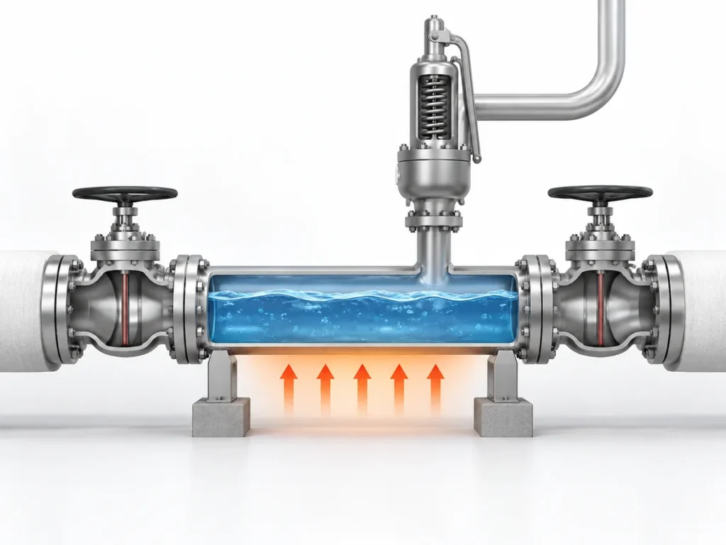
يمكن لصمام الأمان المزود بغلاف أن يحافظ على جسم الصمام ضمن نطاق درجة حرارة مطلوب، لكن ذلك لا يعني تلقائيًا أن أنبوب المخرج المتصل يخضع لنفس التحكم الحراري. فالغلاف يحمي فقط المنطقة الفيزيائية التي يغطيها فعليًا. وبمجرد أن يتجاوز الوسيط عملية المنطقة الساخنة تلك، يصبح لمسار التصريف تعرضه الخاص للظروف المحيطة والعزل وهندسة الأنابيب وأي نظام تتبع حراري منفصل للمخرج أو لخط التصريف.


يمكن لصمام الأمان المزود بغلاف أن يحافظ على جسم الصمام ضمن نطاق درجة حرارة مطلوب، لكن ذلك لا يعني تلقائيًا أن أنبوب المخرج المتصل يخضع لنفس التحكم الحراري. فالغلاف يحمي فقط المنطقة الفيزيائية التي يغطيها فعليًا. وبمجرد أن يتجاوز الوسيط عملية المنطقة الساخنة تلك، يصبح لمسار التصريف تعرضه الخاص للظروف المحيطة والعزل وهندسة الأنابيب وأي نظام تتبع حراري منفصل للمخرج أو لخط التصريف.
لا يهم هذا التمييز إلا عندما يمكن لدرجة الحرارة أن تغيّر بشكل جوهري سلوك الوسيط أو حالة مسار التصريف. في بعض الخدمات، قد يؤدي التبريد إلى زيادة اللزوجة أو التسبب في التجمد أو التصلب أو تعزيز التبلور أو الترسيب أو ترك مادة لا تُصرَّف بسهولة. وفي خدمات أخرى، قد يكون لنفس درجة التبريد تأثير عملي ضئيل. ولهذا ينبغي التعامل مع تتبع المخرج باعتباره قرارًا خاصًا بالخدمة يتعلق بالحدود الحرارية, وليس كملحق تلقائي لكل صمام أمان مزود بغلاف.
السؤال الهندسي الأساسي ليس ببساطة: “هل الصمام مزود بغلاف؟” بل هو:
أين يجب أن ينتهي فعليًا الحفاظ على درجة الحرارة لهذا الوسيط وسيناريو التنفيس هذا وترتيب التصريف هذا؟
الصمام المزود بغلاف والمخرج لا يشتركان تلقائيًا في نفس الحدود الحرارية
A صمام أمان مزود بغلاف يُختار عادةً لأن التحكم في درجة الحرارة حول الصمام نفسه مهم للخدمة. واعتمادًا على التصميم، قد يغطي الغلاف جسم الصمام وقد يمتد حول أجزاء أخرى من الصمام، لكن الحدود الساخنة الدقيقة خاصة بالمنتج ويجب تأكيدها من الرسم المطبق أو بيانات المنتج.
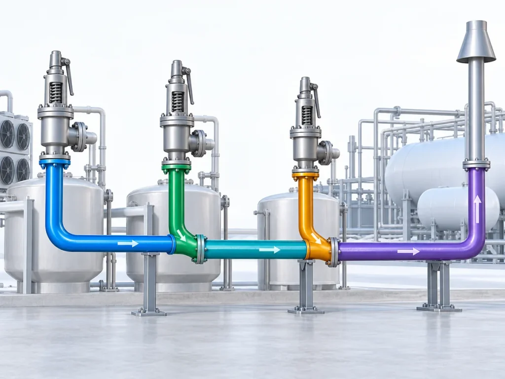
تبدأ الأنابيب النهائية مشكلة حرارية مختلفة. وبمجرد أن ينتقل الوسيط إلى قسم لم يعد مُسخَّنًا بالغلاف، تتأثر درجة حرارته بمادة الأنبوب وقطره والطول المكشوف والعزل والظروف المحيطة والوصلات وفقدان الحرارة الموضعي وأي ترتيب تتبع منفصل. وقد تتصرف وصلة قصيرة معزولة داخل منطقة عملية دافئة بشكل مختلف جدًا عن خط تصريف أطول معرض لدرجة حرارة محيطة منخفضة.
نهاية غلاف الصمام هي حدود المنتج. وليست تلقائيًا نهاية متطلب الحفاظ على درجة الحرارة للعملية.
لا يعني الصمام المزود بغلاف تلقائيًا أنه يجب تتبع المخرج. فإذا بقي الوسيط المصرَّف سائلًا ومستقرًا بشكل مقبول خلال الظروف النهائية ذات الصلة، فقد لا يكون الحفاظ الإضافي على درجة الحرارة مطلوبًا لهذا السبب الحراري. ويعتمد قرار التتبع على ما يفعله تغير درجة الحرارة فعليًا بالخدمة.
ما الذي يمكن أن يتغير عندما تبرد مخرج التصريف
التبريد بحد ذاته ليس آلية الفشل. السؤال المهم هو ما إذا كان التبريد ينقل الوسط إلى نطاق درجة حرارة يتغير فيه سلوكه الفيزيائي بما يكفي للتأثير على مسار التصريف.
بالنسبة لسائل حساس لدرجة الحرارة، قد تؤدي درجة الحرارة المنخفضة إلى زيادة اللزوجة بشكل ملحوظ. وفي خدمة أخرى، قد يتجاوز التبريد حد التجمد أو التصلب. وقد تتبلور وسائط أخرى أو ترسب مواد صلبة أو تتكثف أو تشكل رواسب تحت تركيبات معينة من درجة الحرارة والتركيب والضغط. هذه الآليات ليست متكافئة، ولا ينبغي افتراض أي منها دون معلومات خاصة بالخدمة.
تبريد مخرج التصريف قد يأتي من أكثر من فقدان الحرارة إلى المحيط
التعرض للمحيط هو أحد مصادر تبريد مخرج التصريف، لكنه ليس المصدر الوحيد. في بعض الخدمات، قد يؤدي خفض الضغط أو التبخير الومضي أو تمدد الغاز عبر مسار التنفيس أيضًا إلى خفض درجة حرارة المائع. وقد يكون تأثير التبريد الذاتي هذا مهمًا حيث يمكن للوسط أن يتجمد أو يشكل هيدرات أو يتكثف أو يرسّب مواد صلبة عند درجة الحرارة المنخفضة.
لهذا السبب، ينبغي أن تُستمد درجة حرارة مخرج التصريف المعنية من حالة التنفيس والتجهيز الشتوي الفعلية، وليس من درجة حرارة العملية الطبيعية في المنبع وحدها. ويعتمد ما إذا كانت هذه الآلية مهمة على تركيب المائع وسلوك الطور وتغير الضغط وترتيب التصريف.
يبدأ التقييم من الوسط: تغير درجة الحرارة ← استجابة الوسط, وليس من الصمام.
إذا بقي الوسط قابلاً للتدفق بالكامل خلال نطاق درجة الحرارة المتوقع، فقد لا يُنشئ قسم مخرج التصريف غير المُسخَّن مشكلة حرارية. أما إذا تسبب التبريد في أن يصبح الوسط عالي اللزوجة أو يشكل مواد صلبة أو يتراكم في النقاط المنخفضة، فإن حالة المصب تستحق مراجعة أقرب بكثير.
تغير الوسط ليس بعد نفس الشيء الذي يعنيه وجود تقييد
حتى عندما يغير التبريد اللزوجة أو ينتج مواد صلبة، فإن ذلك لا يعني تلقائيًا أن خط التصريف أصبح مقيّدًا هيدروليكيًا. فكمية المادة المحتجزة ومساحة التدفق المتاحة وهندسة الأنبوب ومعدل التنفيس وخصائص المائع الفعلية كلها عوامل مهمة.
فقط عندما تؤدي الحالة الناتجة إلى زيادة ملموسة في المقاومة عبر مسار التصريف، تصبح مسألة فقدان ضغط.
لا يُثبت تغيّر سلوك الوسط بحد ذاته وجود مشكلة في الضغط الخلفي: تبريد المخرج ≠ الضغط الخلفي المتولّد.
تبريد المخرج
→ قد يغيّر سلوك الوسط
→ قد يُنشئ تراكمًا أو تقييدًا
→ إذا أدّى التقييد إلى زيادة ملموسة في فقدان الضغط، فقد يزداد الضغط الخلفي المتولّد
→ قد يغيّر سلوك الوسط
→ قد يُنشئ تراكمًا أو تقييدًا
→ إذا أدّى التقييد إلى زيادة ملموسة في فقدان الضغط، فقد يزداد الضغط الخلفي المتولّد
وفقًا لمصطلحات ISO 4126-7، الضغط الخلفي المتولّد هو ضغط المخرج الناتج عن التدفق عبر صمام الأمان ونظام تصريفه. أما ما إذا كانت الزيادة في ذلك الضغط تغيّر تشغيل صمام الأمان تغييرًا ملموسًا، فيعتمد على تكوين الصمام، ومقدار الضغط الخلفي وتغيّره، وحدود الشركة المصنّعة، وأساس تصميم نظام التنفيس المعمول به.
لا ينبغي افتراض أن مخرجًا غير متتبَّع يجعل الصمام غير مستقر أو يسبب مشكلة أداء معينة. يجب إثبات النتيجة الهيدروليكية بشكل منفصل.
قد لا تكون الحالة الحرارية الحاكمة هي حدث التنفيس بأقصى تدفق
لا تكون درجة حرارة أقصى تدفق تنفيس دائمًا هي الحالة الحرارية الحاكمة.
قد يكون استخدام درجة حرارة أقصى تدفق تنفيس كأساس حراري وحيد مناسبًا في بعض الأنظمة، لكنه ليس معمّمًا. يمكن أن يمرّ خط التصريف بحالات حرارية مختلفة أثناء التشغيل، والإيقاف، والاستعداد، والتعرّض للبيئة المحيطة، وأحداث تنفيس أصغر، وبعد حدث تنفيس عندما تبقى المادة في جزء من الأنابيب.
A credible leakage, simmering or other small-flow case can also govern the thermal review. A small intermittent or continuous leak can enter an outlet that has cooled toward the winterizing temperature, and some project practices specifically check whether that leaking fluid would freeze, congeal or become excessively viscous under those conditions. This case should be evaluated where it is credible; it should not be assumed for every valve or service.
Consider a system that is normally hot but has long standby periods. The valve body may remain heated by its jacket while the connected outlet section approaches ambient temperature. If a temperature-sensitive fluid enters that cold section during a later event, the initial pipe condition can matter even though the flowing medium itself is hot.
In another service, continuous or repeated flow may keep the outlet sufficiently warm without separate tracing. The controlling condition has to be identified from the actual process rather than assumed from one operating point.
What Determines Whether the Outlet Actually Needs Tracing
The tracing decision becomes much clearer when it is treated as a set of engineering variables instead of a yes-or-no rule attached to the valve type.
| عامل القرار | لماذا هو مهم | ما يجب التحقق منه |
|---|---|---|
| سلوك الوسط | Determines whether cooling changes viscosity, phase, solubility or solids formation | Relevant temperature-property data and composition |
| Required temperature condition | Defines the temperature range needed to maintain acceptable flow behavior | Project or process maintain-temperature basis |
| درجة حرارة التنفيس | Establishes the temperature entering the discharge path during the applicable relief case | Relief calculation / process data |
| Standby, startup and shutdown conditions | The coldest or most restrictive condition may occur outside normal operation | Relevant operating states |
| Minimum ambient temperature | Affects heat loss and cold-start condition | Site design data |
| تغطية الغلاف | Defines where valve-side heating actually stops | Valve drawing or product data |
| Outlet geometry | Length, diameter, fittings and exposed surface affect heat loss and hydraulic behavior | Actual piping layout |
| العزل | Reduces heat loss but does not generate heat | Type, thickness and continuity |
| نقاط التصريف والنقاط المنخفضة | Retained material may experience extended cooling | ترتيب الأنابيب والمصارف |
| وجهة التفريغ | ضغط المجمع وظروف المصب تؤثر على سلوك نظام التنفيس الكلي | تصريف مفتوح أو نظام مغلق أو بيانات المجمع |
| أساس التتبع الحراري | يحدد ما إذا كان النظام المقترح قادرًا على الحفاظ على درجة الحرارة المطلوبة | حساب الفقد الحراري وتصميم التتبع |
| Project requirements | May impose additional design or documentation requirements | Applicable project specification |
No single item in this table decides the question by itself.
For example, knowing that a product begins to crystallize below a certain temperature still does not establish the tracing design. The engineer also needs to know whether the relevant outlet section can actually reach that temperature, how long it remains there, whether insulation is present, whether material remains in the pipe and what temperature the tracing system is expected to maintain.
Likewise, knowing that the site has a low minimum ambient temperature does not prove that tracing is required. If the medium is not sensitive to that temperature or the relevant section remains adequately warm for other reasons, the design conclusion may be different.
A four-step tracing decision path
- Screen the medium. Determine whether, within a credible temperature range, it can become unacceptably viscous, freeze, solidify, crystallize, condense, form hydrates or otherwise create a restriction.
- Screen the outlet temperature. Determine whether the outlet can actually reach that range during relief, leakage or simmering, standby, startup, shutdown or post-relief conditions, including ambient heat loss and any relevant expansion or flashing cooling.
- Check passive heat retention. Determine whether the actual pipe geometry, retained process heat and insulation are sufficient to keep the outlet above the required maintain-temperature basis without active tracing.
- Design and verify separately. If active temperature maintenance is still required, perform the heat-loss and tracing design, then separately verify drainage, outlet hydraulics, back pressure, supports and safe discharge.
Use this sequence for screening and specification. The project heat-loss calculation and relief-system hydraulic analysis remain separate requirements.
There is no universal tracing length
A fixed instruction such as “trace the first one metre after the valve” is not a reliable general rule.
Required tracing coverage depends on the thermal duty. Pipe diameter, length, material, ambient temperature, insulation, fittings, equipment surfaces and the required maintain temperature all influence heat loss. A short uninsulated metallic outlet can present a different duty from a longer, well-insulated discharge line.
The maintain temperature also should not be chosen simply because the valve or upstream process operates at a particular temperature. The relevant target is the temperature needed to keep the medium within an acceptable condition for the actual service, while also respecting any product or material temperature limits.
Representative engineering scenario
Consider a jacketed safety valve protecting equipment that contains a temperature-sensitive liquid. The valve jacket maintains the valve region at the required process condition, but the outlet piping leaves the heated area and passes through a colder location.
The decision should not be reduced to: jacketed valve → trace the outlet.
A more reliable sequence is:
- Confirm where the valve jacket actually ends.
- Determine the temperature-sensitive behavior of the medium.
- Identify the relevant thermal condition during standby, startup, relieving and post-relief periods.
- Estimate or calculate the temperature condition of the outlet section.
- Determine whether that condition could create unacceptable viscosity, phase change or solids behavior.
- If temperature maintenance is needed, design the tracing and insulation for that thermal duty.
- Independently verify the outlet hydraulics, drainage and back-pressure conditions.
This sequence is illustrative, not a recorded customer case or a universal tracing specification.
What Outlet Tracing Cannot Fix
Outlet tracing can address a thermal problem. It cannot convert an otherwise unsuitable discharge system into an acceptable one.
If the discharge piping is undersized, unnecessarily restrictive or connected to a system with excessive downstream pressure, heat tracing does not correct the hydraulic design. If the piping traps liquid because of poor drainage or unsuitable low points, tracing does not eliminate the need to review the piping arrangement . It also does not establish that reaction forces, supports or safe discharge requirements have been addressed.
Different controls solve different problems
| التحكم | What it does | ما لا يغني عنه |
|---|---|---|
| Heat tracing | Adds heat to maintain a required temperature condition where the thermal duty justifies it. | Does not correct undersized or overly restrictive discharge piping and does not by itself prove acceptable back pressure. |
| العزل | Reduces heat loss and helps preserve available process or tracing heat. | Does not generate heat and does not correct retained liquid, poor drainage or an unsuitable piping layout. |
| Slope and drainage | Reduce the opportunity for liquid or residual material to remain in low points and cool for extended periods. | Do not maintain temperature and do not replace tracing where active heat input is actually required. |
| Outlet hydraulic design | Addresses piping size, layout, pressure loss and the resulting back-pressure condition for the relief system. | Does not keep a temperature-sensitive medium warm or prevent phase change and solids behavior by itself. |
The same boundary applies to safety-valve capacity. Adding heat tracing does not increase or prove the valve’s certified relieving capacity. Capacity remains dependent on the selected valve, orifice or flow area, service conditions and the applicable manufacturer or certification basis.
الضغط الخلفي must also remain a separate check. If a temperature-related deposit reduces the effective flow path enough to increase pressure loss, built-up back pressure may rise. But the size of that effect cannot be inferred from the presence of deposits alone. It requires the actual relieving flow, outlet geometry, fluid properties and downstream pressure conditions.
Similarly, the resulting effect on the safety valve depends on the design being used. A conventional spring-loaded valve, a balanced bellows design and a pilot-operated valve do not have identical back-pressure behavior or limitations. Outlet tracing therefore should never be presented as a substitute for selecting and verifying the correct relief-device configuration.
What to Verify Before Specifying Outlet Tracing
A useful tracing specification should begin with service information rather than with a standard tracing temperature or a fixed length of pipe.
Before deciding the outlet treatment, confirm the following.
Medium and thermal behavior
Identify the medium, phase and composition closely enough to understand the temperature-dependent behavior that matters to the discharge path. Depending on the service, the relevant concern may be viscosity, freezing, solidification, crystallization, precipitation, condensation or another documented limitation.
Only properties that can change the tracing decision need to be established.
Relevant temperatures and operating states
Confirm the normal operating temperature and the relieving temperature, but also consider the conditions that may leave the outlet cold before a relief event. Minimum ambient temperature, startup, shutdown and standby conditions may be important where the process is intermittent.
A tracing design also needs a defined maintain-temperature basis. That temperature should come from the process requirement and validated medium behavior, not from a generic rule for jacketed valves.
Valve and piping boundary
Confirm the actual jacket coverage from the applicable product information. Then review the outlet diameter, length, material, fittings, insulation, exposed sections, low points, drainage and discharge destination.
This establishes where separate thermal control may be needed and provides the information required for a heat-loss or tracing design.
Relief-system conditions
Confirm the discharge arrangement and relevant back-pressure conditions independently of the tracing decision.
If the valve discharges into a closed header, existing superimposed back pressure and the additional built-up back pressure during relieving may both be relevant. If a thermal restriction is considered credible, its potential hydraulic consequence must be evaluated rather than assumed.
Tracing and insulation design
If the assessment shows that the outlet requires temperature maintenance, the tracing system should be designed for the actual thermal duty.
That normally means considering the required maintain temperature, minimum ambient condition, pipe geometry, insulation, heat loss, startup requirement and any equipment or fitting allowances. The choice between steam tracing and electric heat tracing should follow the project conditions and available utilities; neither method should be treated as universally preferable.
The final specification should also make the responsibility boundary clear. The valve manufacturer may need to confirm the jacket configuration and product temperature limits, while the process, piping or heat-tracing engineer may own the downstream thermal and piping design. Project responsibilities should be defined rather than assumed.
Pre-Specification Checklist
Before releasing the tracing requirement, verify that the project has enough information to answer these questions:
- What medium and phase can enter the discharge line?
- What temperature-dependent behavior creates the thermal concern?
- What is the relevant operating or relieving temperature?
- What are the important startup, shutdown or standby conditions?
- What minimum ambient condition applies?
- Where does the valve jacket actually end?
- What outlet piping remains outside that heated region?
- Is that piping insulated?
- Can material remain in low points or poorly drained sections?
- إلى أين يتم تصريف الصمام؟
- What back-pressure conditions apply?
- What temperature must the downstream piping actually maintain?
- Has the tracing duty been checked against the real pipe and insulation arrangement?
- Which requirements come from the process design, valve manufacturer and project specification?
If those questions cannot yet be answered, do not assign a tracing temperature or length. Close the missing engineering inputs first.
Safety and code boundary
API 520 الجزء الثاني addresses pressure-relief-device installation, while API 521 addresses pressure-relieving and depressuring systems, including disposal-system engineering. ISO 4126 provides additional safety-device terminology and technical framework. Those scopes are relevant to the wider relief-system review, but their names alone do not establish a universal requirement to heat-trace the outlet of every jacketed safety valve.
The applicable edition, project specification, process conditions and valve/manufacturer data still have to be confirmed.
Final design still requires the project relief calculation, piping review, manufacturer data and the applicable jurisdiction-specific code assessment.
أسئلة متكررة
Does every jacketed safety valve need outlet heat tracing?
No. A jacketed valve only establishes the heated boundary of the valve itself. Separate outlet tracing is justified when the actual service and downstream conditions show that temperature loss could make the medium unacceptably viscous, cause phase change or solids formation, or otherwise create a credible restriction in the discharge path.
Where should outlet tracing start and stop?
There is no universal fixed length. The required coverage depends on where the valve jacket ends, the outlet geometry, insulation, ambient condition, the medium’s temperature-dependent behavior and the maintain-temperature basis for the service. The tracing boundary should come from the thermal duty rather than from a generic distance after the valve.
Can insulation replace heat tracing on the outlet?
Not when active heat input is required. Insulation reduces heat loss, but it does not generate heat. In some services, insulation and retained process heat may be sufficient to keep the outlet within the required temperature range; in others, active tracing is still needed.
Can outlet cooling increase built-up back pressure?
It can contribute only through a conditional chain. Cooling may change the medium, that change may create deposits, retained material or another restriction, and the restriction must materially increase discharge-line pressure loss before built-up back pressure increases. Cooling by itself is not the same as a back-pressure problem.
Can outlet tracing correct undersized or poorly arranged discharge piping?
No. Tracing addresses temperature maintenance. It does not correct an undersized or overly restrictive outlet, poor drainage, unsuitable low points, excessive downstream pressure, support problems or an otherwise unacceptable relief-system layout. Those issues require separate piping and hydraulic verification.
What information should be confirmed before specifying outlet tracing?
Confirm the process medium and phase, relevant temperature-dependent behavior, normal and relieving temperatures, minimum ambient condition, startup/shutdown/standby cases, actual valve-jacket coverage, outlet piping geometry, insulation, drainage and low points, discharge destination, back-pressure conditions, and the required maintain temperature. Those inputs determine whether tracing is needed and, if it is, the thermal duty it must satisfy.
Need help reviewing the outlet thermal boundary?
For an engineering review, provide the process medium and phase, normal and relieving temperatures, minimum ambient condition, set pressure and relevant relief scenario, the jacketed-valve configuration, available jacket drawing, outlet piping arrangement, discharge destination, insulation and any existing tracing or project requirements.
With those inputs, the discussion can focus on the actual question: where temperature maintenance needs to continue, and which parts of the relief-system design still require separate verification.
اسأل مهندسًا