Erfahren Sie, wie Chlorbedingungen, Komponentenwerkstoffe, Berstscheiben-Absicherung, Gegendruck und Abblaseleitung die Auslegung von Sicherheitsventilen beeinflussen.

Sicherheitsventile für Chloranwendungen sollten nicht einfach durch die Wahl eines “korrosionsbeständigen” Gehäusewerkstoffs ausgewählt werden. Der tatsächliche Chlorzustand, die Komponenten, die damit in Berührung kommen können, die Druckentlastungsanordnung und das Ziel des Abblasens beeinflussen die endgültige Spezifikation. Ein Werkstoff, der unter einem Chlorzustand akzeptabel ist, kann unter einem anderen ungeeignet sein, und ein nachgeschaltetes Rückhaltesystem kann einen Gegendruck oder eine sekundäre Exposition einbringen, die zusammen mit dem Ventil und nicht erst danach berücksichtigt werden müssen.
Die praktische Auswahlreihenfolge ist daher: die Chloranwendung definieren, feststellen, welche Teile der Entlastungseinrichtung mit dieser Anwendung in Berührung kommen können, Werkstoffe Komponente für Komponente prüfen, jede Absperranordnung als Teil des Druckentlastungssystems bewerten und dann den Entlastungspfad in das Abblase- oder Rückhaltesystem verfolgen. Die endgültige Auswahl erfordert weiterhin das maßgebliche Entlastungsszenario, die erforderliche Abblaseleistung, Herstellerdaten, den anwendbaren Code oder Standard und projektspezifische Abnahmeanforderungen.
Sicherheitsventile für Chloranwendungen: Zuerst die Bedingungen definieren
“Chloranwendung” ist zu weit gefasst, um als Werkstoffspezifikation zu dienen. Bevor Ventilwerkstoffe oder Konfigurationen verglichen werden, muss der Ingenieur wissen, welchem Chlorzustand die Einrichtung während des Normalbetriebs und während eines Entlastungsereignisses tatsächlich ausgesetzt sein kann.
Die erste Unterscheidung ist die Phase. Gasförmiges oder dampfförmiges Chlor, flüssiges Chlor und jeder glaubhafte gemischte oder sich ändernde Zustand stellen nicht automatisch die gleichen Anforderungen an Werkstoff oder Auslegung. Die zweite ist die Feuchtigkeit. Trockenes und feuchtes Chlor dürfen nicht als austauschbare Umgebungen behandelt werden. Die aktuelle Sicherheitsleitlinie für Chloralkali macht diesen Unterschied besonders wichtig: Werkstoffe, die unter kontrollierten Trockenchlor-Bedingungen akzeptabel sind, können bei Feuchtigkeitseintrag unakzeptabel werden, während ein anderer Werkstoff in trockenem Chlor eine ernste Gefahr darstellen kann, obwohl er sich unter feuchten Bedingungen anders verhält.
Dieser Gegensatz ist nützlicher als eine universelle Werkstofftabelle, weil er erklärt, warum die Anwendungsbedingungen zuerst definiert werden müssen. Beispielsweise warnt die CCPS-Leitlinie davor, Kohlenstoffstahl und Titan so zu behandeln, als ob ihr Verhalten unverändert zwischen trockenen und feuchten Chlorumgebungen übertragen werden könnte. Die technische Lehre ist nicht, dass ein Werkstoff universell “gut” und ein anderer universell “schlecht” ist. Sie lautet, dass die Chlorverträglichkeit zu einer definierten Kombination aus Mediumzustand, Temperatur, Werkstoff, Komponentenexposition und Projektanforderungen gehört.
Feuchtigkeit sollte auch nicht auf einen universellen ppm-Grenzwert für jedes Chlorsystem reduziert werden. Der akzeptable Zustand hängt vom relevanten Prozess, Druck, Temperatur, Anlagenumfang und der maßgeblichen Spezifikation ab. Wenn das Projekt einen Feuchtigkeitsgrenzwert für Trockenchlor definiert, sollte dieser Grenzwert in die Ventilspezifikation übernommen werden. Wenn nicht, sollte der Ingenieur keinen aus einem allgemeinen Artikel oder einem unabhängigen Rohrleitungsbeispiel erfinden.
Die Temperatur ist aus demselben Grund wichtig. Die normale Betriebstemperatur kann nicht mit der Entlastungstemperatur übereinstimmen, und letztere kann sowohl die Werkstoffeignung als auch die Druckentlastungsberechnung beeinflussen. Verunreinigungen oder Prozessverschleppung können die Exposition ebenfalls verändern, verglichen mit dem, was die einfache Bezeichnung “Chlor” vermuten lässt.
Vor Beginn der Werkstoffauswahl sollte die Anwendungsdefinition daher, soweit zutreffend, Folgendes festlegen:
- das geschützte Equipment und das maßgebliche Entlastungsszenario;
- ob das Chlor gasförmig, dampfförmig, flüssig ist oder während der Entlastung seinen Zustand ändern kann;
- die anwendbare Feuchtigkeitsbedingung und jede projektspezifische Feuchtigkeitsspezifikation;
- relevante Verunreinigungen oder Kontaminationen;
- Betriebs- und Entlastungstemperaturen;
- Betriebsdruck, Auslegungsdruck oder MAWP und Ansprechdruck;
- sowie alle nachgeschalteten Bedingungen, die das Ventil einer anderen Umgebung als der Prozessseite aussetzen können.
Diese Informationen allein legen das Ventil nicht fest. Sie definieren die Umgebung, vor deren Hintergrund das Ventil bewertet werden kann.
Werkstoffe nach Bauteil-Exposition auswählen, nicht nur nach dem Gehäusewerkstoff
Sobald die Chlorbedingungen definiert sind, lautet die nächste Frage nicht einfach “Welchen Gehäusewerkstoff sollen wir verwenden?” Die hilfreichere Frage ist: Welche Bauteile kommen tatsächlich mit Chlor in Kontakt, unter welchen Bedingungen und wie lange?
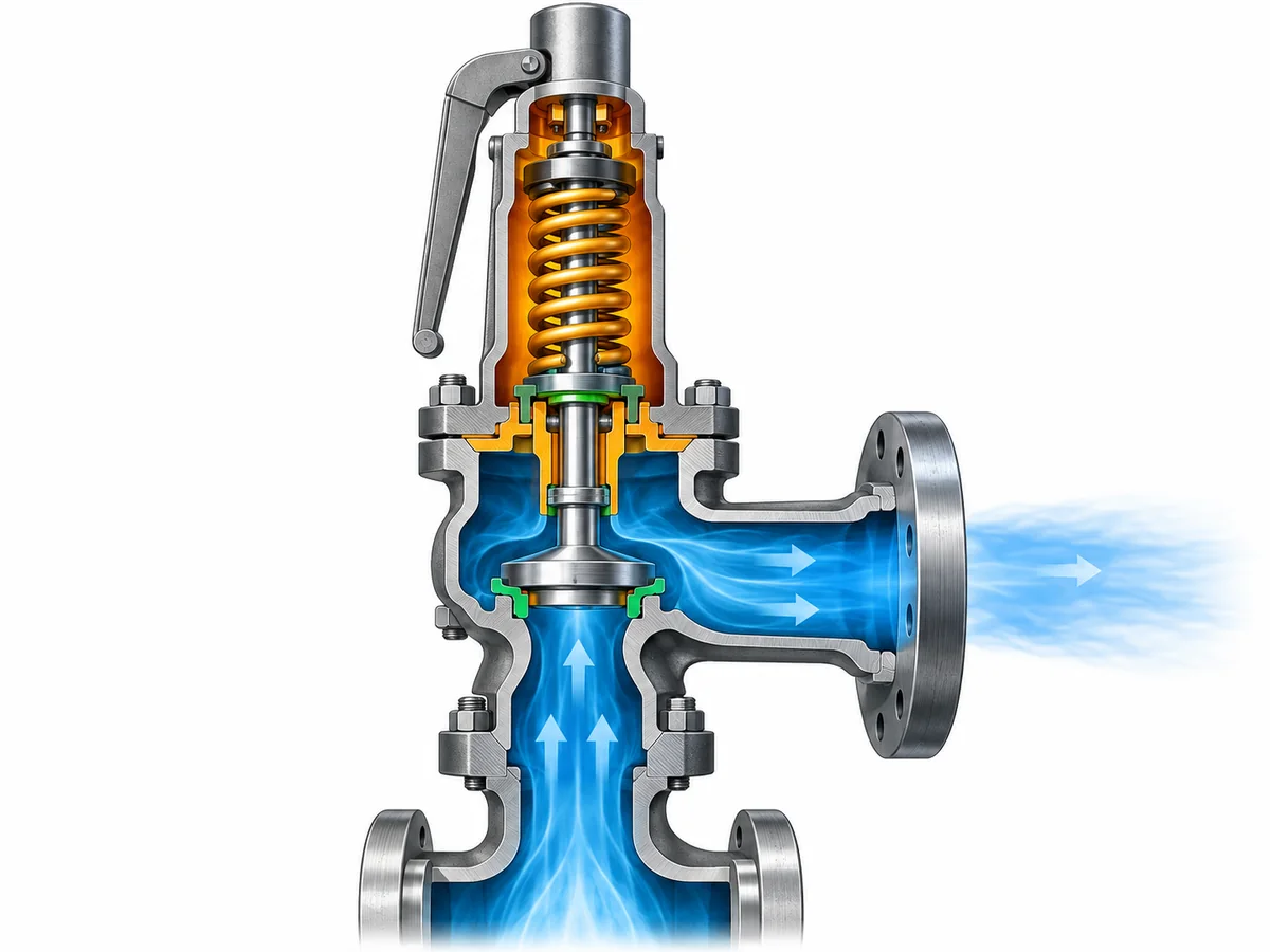
A safety valve is a system of pressure-retaining, moving, guiding, sealing, and spring-loaded components. Depending on the design, these parts may not share the same exposure. The body and nozzle may be process-wetted continuously. The disc and guide may be exposed differently during normal service and during opening. A bellows, spring, spindle, gasket, soft seat, O-ring, or other seal may have its own exposure path and material limitation.
That is why whole-valve suitability cannot be established by approving the body grade alone.
Separate metallic and nonmetallic decisions
Metallic compatibility and nonmetallic compatibility should be reviewed separately. A metallic body and trim combination that is acceptable for the defined chlorine condition does not prove that a soft seat, elastomer, gasket, or seal is equally suitable. Conversely, a gasket listed for one chlorine condition does not certify an entire valve assembly.
For each relevant component, the engineering review should identify:
- whether the component is continuously process-wetted, intermittently exposed, exposed only during relief, or isolated from the process under normal conditions;
- the chlorine state and temperature at that exposure;
- whether moisture or contaminants can change the corrosion environment;
- the exact material grade or compound proposed;
- the manufacturer or project evidence supporting that material in the defined condition; and
- any temperature, pressure, aging, maintenance, or inspection limitation that remains.
For springs and bellows, exposure deserves particular care because it is design-dependent. It is unsafe to assume that every spring is isolated from the process or that every bellows sees exactly the same environment as the valve inlet. Bonnet arrangement, venting, internal leakage paths, and the specific valve design determine what must be reviewed.
The same discipline applies to material equivalence. A similar grade name, approximate chemistry, or cross-standard correspondence is not enough to prove equivalent chlorine performance or project acceptance. If the project requires a particular material specification, heat condition, certification, or traceability level, the exact requirement should remain attached to the purchase specification.
The useful output from this step is therefore not a generic “best materials for chlorine” list. It is a component-exposure map that lets the engineer ask the correct compatibility question for each part of the valve.
Evaluate Whether the Safety Valve Needs Process Isolation
In some corrosive services, an upstream rupture disc can be considered to reduce normal exposure of the pressure relief valve to the process medium. For chlorine service, that can be a useful engineering option—but it is not an automatic requirement and should not be treated as a corrosion shortcut.
Adding a rupture disc changes the protection system. The disc and valve are no longer independent devices that can simply be selected separately and installed in series.
A combination arrangement introduces at least three additional questions.
First, the relieving capacity must be verified for the combination. The standalone capacity of the valve should not automatically be assumed to remain the certified or documented capacity of the assembled rupture-disc/PRV system. The applicable code basis and manufacturer data need to support the combination being used.
Second, the space between the rupture disc and the valve matters. If pressure accumulates in that interspace, it changes the differential pressure acting across the rupture disc and can therefore change its behavior. The arrangement may require venting, pressure indication, monitoring, or another approved method of detecting pressure in that cavity. The exact method depends on the device design, code basis, and project specification.
Third, isolation changes the exposure pattern rather than eliminating the material problem. Under normal operation, the rupture disc may reduce direct contact between the process and the relief valve. During a relief event, after disc opening, or if leakage occurs, the PRV can still be exposed to chlorine. The rupture disc itself, its holder, gaskets, the interspace connection, and the downstream valve components still require appropriate materials.
This creates a real engineering trade-off. Isolation can reduce normal corrosive exposure of the valve, but it adds another pressure-relief device, another material interface, another capacity relationship, and additional inspection and monitoring responsibilities.
Does the defined process and maintenance strategy justify isolating the PRV, and can the disc-and-valve combination be verified as a complete pressure-protection system?
If the answer is yes, the RFQ should identify the proposed combination arrangement and require the manufacturer or engineering authority to confirm the capacity basis, material compatibility, interspace treatment, pressure relationships, installation details, and applicable code requirements.
Design the Discharge Path as Part of the Valve Specification
A chlorine-service relief device cannot be specified responsibly without knowing where the discharge goes.
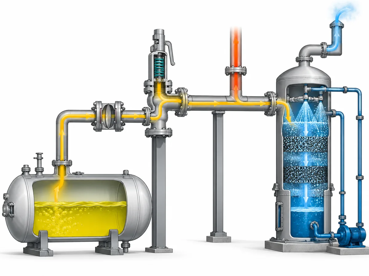
Depending on the facility and governing requirements, relieved chlorine may be routed to a closed receiver, treatment system, scrubber, common relief header, or another approved destination. The correct destination is project- and jurisdiction-specific. This article does not establish that every chlorine relief must discharge to a scrubber, nor does it establish that atmospheric discharge is acceptable for a particular installation.
The engineering point is that the discharge destination can feed back into the valve decision.
Containment can create back pressure
A relief valve discharging into a closed system may see Überlagerter Gegendruck before it opens and Aufbauender Gegendruck as relief flow passes through the outlet piping, header, receiver, or treatment equipment.
Those pressures can affect valve operation, available relieving capacity, stability, and configuration selection. The magnitude and variability of back pressure therefore need to be evaluated against the selected valve’s documented limits. Simply specifying a balanced bellows or pilot-operated design does not make every back-pressure problem disappear; those configurations also have application limits that must be confirmed against manufacturer data and the actual system.
The discharge system should be evaluated as a flow path rather than a destination label. Relevant questions include:
- What pressure already exists at the valve outlet before relief begins?
- How much additional pressure can be generated while the required relief flow passes through the outlet system?
- Does the discharge header serve other relief devices that can operate simultaneously?
- Can liquid collect in the outlet piping?
- Is drainage required?
- Are reaction loads and pipe supports addressed?
- Can downstream vapor, condensate, liquid, or contamination reach the valve under credible operating conditions?
The last question is especially important in chlorine service because moisture can materially change corrosion behavior. That does nicht mean that every closed relief header will introduce moisture into the valve. It means that if the actual piping arrangement makes downstream exposure or backflow credible, that exposure belongs in the material review.
Containment and material selection are connected
Consider a representative engineering scenario. A process system contains chlorine under a controlled dry condition, while the relief outlet connects to a treatment system. The valve body material might initially be screened against the process-side dry condition. But if the downstream arrangement can subject outlet-side components to a different vapor condition, condensation, liquid accumulation, or back pressure, the engineer has two distinct environments to consider.
That scenario is illustrative, not a recorded project. Its value is the decision logic: material suitability must follow actual exposure paths, and those paths do not necessarily stop at the valve inlet.
The same reasoning applies when a rupture disc is installed upstream. Normal process exposure may be reduced, but relief-event exposure and downstream conditions still need to be considered. The pressure-protection system must work as a whole—from protected equipment, through any isolation device and relief valve, into the disposal or containment system.
Build the Chlorine-Service Verification Package Before RFQ
An RFQ that says only “Need a chlorine-compatible safety valve” leaves the most important engineering questions unanswered.
A supplier cannot safely establish material suitability, configuration, capacity, or documentation requirements from the medium name and connection size alone. Connection size is not relieving capacity, set pressure is not relieving capacity, and a material description is not a sizing basis.
A useful chlorine-service RFQ should provide enough information to evaluate both the service-compatibility problem und im pressure-relief problem.
| Input to provide | Warum es die Entscheidung beeinflusst |
|---|---|
| Geschützte Ausrüstung und maßgebliches Entlastungsszenario | Establishes what event the valve must protect against and forms the basis for required relieving load. |
| Chlorine phase and process composition | Affects both sizing and material exposure. |
| Moisture condition or project dry-chlorine specification | Can materially change corrosion and compatibility decisions. |
| Operating pressure and design pressure/MAWP | Establishes the pressure relationship surrounding the set point and normal operating margin. |
| Ansprechdruck | Defines the valve’s opening pressure basis but does not establish capacity. |
| Erforderliche Entlastungskapazität und Berechnungsbasis | Provides the load the selected device or device combination must be able to relieve. |
| Betriebs- und Entlastungstemperatur | Influences material suitability and the relieving calculation. |
| Überlagerter und aufgebauter Gegendruck | Can affect valve configuration, capacity and stability. |
| Anordnung der Einlass- und Auslassleitungen | Identifies pressure-loss, support, discharge and exposure issues that cannot be seen from the valve datasheet alone. |
| Proposed rupture disc or isolation arrangement, if any | Triggers combination-capacity, material, monitoring and installation review. |
| Required body, trim, seat, seal, gasket, spring or bellows materials | Allows component-level compatibility review instead of body-grade-only selection. |
| Discharge destination or containment concept | Establishes the downstream conditions the relief device must operate against. |
| Applicable code, jurisdiction and project specification | Defines the actual acceptance basis; a standard name should not be assumed from the service alone. |
| Required inspection, material and test documentation | Establishes traceability and acceptance deliverables before quotation or order. |
Where an existing valve is being replaced, the old nameplate and connection dimensions can help identify the existing device, but they do not establish a safe direct replacement. Capacity basis, materials, service condition, back pressure, configuration, documentation, and project requirements still need to be checked.
The same caution applies to catalog data. A manufacturer’s general material matrix can identify available construction options, but it should not be converted automatically into a chlorine-suitability statement. Exact suitability belongs to the selected product configuration and the defined service condition.
Before requesting a final valve selection, assemble the chlorine condition, relief scenario, required capacity, pressure and temperature basis, back pressure, material requirements, any rupture-disc arrangement, discharge destination, and documentation requirements. With those inputs available, an engineering review can determine which product configuration and material set should be evaluated against the actual project.
Ask a Safety Valve Engineer: send the operating and relieving conditions, required relieving capacity or calculation basis, chlorine condition, discharge arrangement, back pressure, proposed materials, applicable project requirements, and any existing valve or rupture-disc data. The review should confirm suitability and capacity from the selected product data rather than assuming them from a generic chlorine-service description.