Erfahren Sie, wann ein externer Brand zu einem Entlastungsfall für Druckbehälter wird, welche Faktoren die Entlastungslast bestimmen und wie das Ergebnis in die PSV-Auslegung einfließt.


Externe Brandeinwirkung sollte nicht als Abkürzung von “Druckbehälter” zu “größeres Sicherheitsventil” behandelt werden. Sie ist zunächst eine Frage des Entlastungsfalls. Der Ingenieur muss feststellen, dass ein glaubwürdiger Brand den geschützten Behälter beaufschlagen kann, ermitteln, wie sich diese Beaufschlagung auf den Behälterinhalt auswirkt, die daraus resultierende erforderliche Abblaseleistung nach der geltenden Auslegungsgrundlage berechnen und erst dann das Druckentlastungsventil auslegen und verifizieren.
Diese Reihenfolge ist wichtig, weil mehrere unterschiedliche ingenieurtechnische Verantwortlichkeiten leicht zu einer einzigen zusammengefasst werden. Die Größe eines Behälters ist nicht seine erforderliche Abblaseleistung. Der Ansprechdruck ist nicht die Abblaseleistung. Die Anschlussgröße eines Ventils ist kein Nachweis der Durchflusskapazität. Und ein Druckentlastungsventil, das die berechnete Brandlast abführen kann, beweist für sich genommen nicht, dass der Behälter während eines schweren Brandes mechanisch intakt bleibt.
Für einen typischen flüssigkeitsgefüllten Behälter, der einem glaubwürdigen Poolbrand ausgesetzt ist, verläuft die ingenieurtechnische Kette im Wesentlichen wie folgt:
glaubwürdige Brandeinwirkung → Wärmeeintrag in den Behälter und den Flüssigkeitsinhalt → Fluidreaktion und Dampfbildung → erforderliche Abblaseleistung → PSV-Auslegung und Kapazitätsverifikation → Prüfung von Einlass, Auslass und Abblasesystem.
Diese Kette ist nützlich, aber nicht universell. Rein gasförmige, weitgehend unbenetzte, überkritische, reaktive, mehrkomponentige oder potenziell zweiphasige Systeme können eine andere analytische Behandlung erfordern. Die erste Aufgabe besteht daher darin, festzustellen, welches Brandszenario und welches Reaktionsmodell tatsächlich anzuwenden sind.
Wann externe Brandeinwirkung zum maßgeblichen Entlastungsfall wird
Externe Brandeinwirkung ist eine anerkannte Ursache für Überdruck in API 521 Druckentlastungssysteme, aber die Existenz eines Druckbehälters macht den Brand nicht automatisch zum maßgeblichen Fall. Das Szenario muss für die tatsächliche Installation glaubwürdig sein.
Diese Glaubwürdigkeitsbewertung beginnt beim geschützten Equipment und nicht beim Sicherheitsventil. Der Ingenieur sollte feststellen, wo sich der Behälter befindet, welche glaubwürdige Brandquelle ihn beaufschlagen könnte, ob ein anhaltender Poolbrand oder eine andere relevante Brandeinwirkung plausibel ist, welcher Inhalt vorhanden sein kann und welche Projekt- oder Regelwerksgrundlage die Bewertung bestimmt. Layout, Entwässerung, Brandschutz und andere Schutzmaßnahmen können diese Bewertung beeinflussen, sollten aber nicht automatisch als Gründe für den Entfall des Brandfalls behandelt werden.
In einem breiteren Anwendungen von Sicherheitsventilen für Druckbehälter, kann derselbe Behälter auch andere Überdruckszenarien aufweisen – wie blockierter Auslass, Ausfall von Versorgungseinrichtungen, Regelventilausfall, Rohrbruch im Wärmetauscher oder Wärmeausdehnung. Der Brand ist daher ein Kandidatenszenario in der gesamten Entlastungsgrundlage. Der Auslegungsprozess identifiziert die glaubwürdigen Szenarien, berechnet die erforderliche Last für jedes Szenario mit einer geeigneten Methode und legt dann fest, welcher Fall die Druckentlastungsanforderung bestimmt.
Diese Unterscheidung verhindert einen häufigen Auslegungsfehler: mit einer vertrauten “Brandfall”-Ventilgröße zu beginnen, bevor der tatsächliche Brandfall definiert wurde. Das Ventil steht am Ende der Szenarioanalyse. Es kann das Szenario für den Ingenieur nicht festlegen.
Warum Brandeinwirkung eine Entlastungslast im Druckbehälter erzeugt
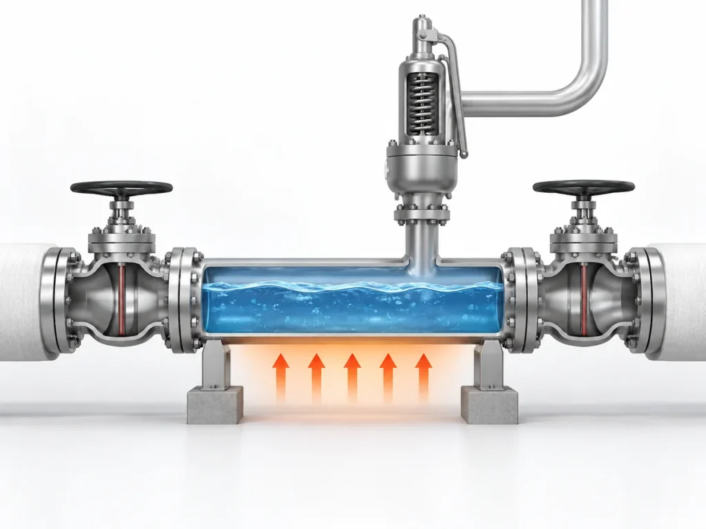
Bei einem geeigneten flüssigkeitshaltigen Behälter beginnt der klassische äußere Brandfall damit, dass Wärme durch die brandexponierte, flüssigkeitsbenetzte Wand in den Behälter eindringt. Die enthaltene Flüssigkeit nimmt diese Energie auf. Während der Inhalt unter Druck erwärmt wird, kann die Dampfbildung zunehmen und den Entlastungsbedarf erzeugen, den das Druckentlastungssystem bewältigen muss.
Entscheidend ist, dass der Entlastungsbedarf durch das Zusammenspiel von Brand und Prozessinhalt entsteht. “Äußerer Brand” ist daher nicht einfach eine Vorgabe der Außentemperatur für das Ventil. Er verändert die Energiebilanz des geschützten Systems.
Für einen einfachen Fall der Flüssigkeitsverdampfung ist das Berechnungskonzept geradlinig. Mit einer geeigneten Brandmethode wird der aufgenommene Wärmeeintrag ermittelt. Der thermodynamische Zustand des Fluids im Entlastungszustand wird dann verwendet, um zu bestimmen, wie dieser Wärmeeintrag in Dampfbildung umgesetzt wird. Das Ergebnis ist eine erforderliche Abblaseleistung – kein Ventilmodell und keine Anschlussgröße.
Der Pfad der Flüssigkeitsverdampfung hat Grenzen
Diese Überlegung sollte nicht unverändert auf jeden Behälter übertragen werden.
Wenn der Behälter wenig oder keine Flüssigkeit enthält, kann der Brand eine weitgehend unbenetzte Metallwand und einen Gas- oder Dampfinhalt erwärmen. Ein überkritisches Fluid verhält sich nicht wie eine konventionell siedende Flüssigkeit. Mehrkomponentengemische können ihre Zusammensetzung ändern, während Material verdampft. Einige Systeme können eine Zweiphasenströmung entwickeln. Reaktive Betriebsbedingungen können zusätzliche Wärmeerzeugungsmechanismen einbringen.
Diese Fälle können eine detailliertere instationäre Massen- und Energieanalyse erfordern statt einer einfachen Näherung der Flüssigkeitsverdampfung.
Es gibt außerdem ein separates Problem der mechanischen Integrität. Eine Druckentlastungseinrichtung begrenzt den Druck durch Abführen von Masse aus dem geschützten System, kühlt aber nicht jeden Teil der Behälterwand gleichmäßig. Eine unbenetzte Wand, die einem schweren Brand ausgesetzt ist, kann sich schnell erwärmen und an Festigkeit verlieren. In einigen Fällen können daher Notentspannung, thermische Reaktionsanalyse oder andere Brandschutzmaßnahmen von Bedeutung sein, selbst wenn die Entlastungseinrichtung eine ausreichende Durchflusskapazität hat.
Die praktische Konsequenz ist, dass der Ingenieur den Inhalt und den Reaktionsmodus identifizieren sollte, bevor er die Brandberechnungsmethode wählt:
- flüssigkeitshaltig und geeignet durch eine empirische Poolbrand-Methode dargestellt;
- gas- oder dampfdominiert;
- überkritisch;
- Mehrkomponenten- oder potenziell zweiphasig;
- reaktiv oder anderweitig außerhalb des einfachen Verdampfungsmodells.
Die Berechnung sollte dieser physikalischen Identität folgen, nicht der Bequemlichkeit einer vertrauten Gleichung.
Bildplatzhalter: Eine zukünftig freigegebene Darstellung kann später ergänzt werden.
Zweck: Den Pfad der Brandreaktion mit flüssigkeitsbenetzter Wand mit nicht einfachen Gas-, Dampf-, unbenetzten, überkritischen oder komplexen Phasenpfaden vergleichen, ohne neue Aussagen hinzuzufügen.
Welche Eingabedaten den Entlastungsbedarf im Brandfall steuern
Ein plausibler Brandfall kann dennoch falsch berechnet werden, wenn die Eingabedaten nicht den tatsächlichen Behälter und die Entlastungsbedingung beschreiben. Die folgenden Eingabedaten sind keine generische Checkliste zum mechanischen Ausfüllen; jeder Punkt ist wichtig, weil er einen bestimmten Teil der technischen Kette verändern kann.
| Eingangsgröße | Warum es für den Brandfall wichtig ist | Was festgelegt werden muss |
|---|---|---|
| Geschütztes Behältnis und Brandeinwirkung | Legt fest, ob das Szenario glaubhaft ist und welcher Teil der Ausrüstung betroffen ist | Behälteridentität, Standort, glaubhafte Brandquelle und anwendbare Brandgrundlage |
| Inventar und Flüssigkeitsstand | Kann die benetzte Fläche, Wärmeaufnahme und mögliches Abblaseverhalten verändern | Glaubhaftes Inventar und Flüssigkeitsstand für den Entlastungsfall |
| Flüssigkeitszusammensetzung und -phase | Bestimmt, wie aufgenommene Wärme in Druckanstieg oder Dampfbildung umgesetzt wird | Flüssigkeit, Dampf, Gas, überkritisch, Mehrkomponenten-, reaktives oder mögliches Zweiphasenverhalten |
| Betriebsdruck und MAWP/Auslegungsgrundlage | Legt den normalen und den geschützten Druckkontext fest | Korrekte Projektdefinitionen statt austauschbarer Druckbegriffe |
| Ansprechdruck-Grundlage | Influences the pressure at which the relief device begins to act | Project/code basis and selected protection philosophy |
| Entlastungsdruck und -temperatur | Control fluid properties and the sizing condition | Values derived from the governing design basis |
| Wetted/exposed area basis | Influences empirical fire heat input for applicable liquid cases | Geometry and liquid-wetted portion allowed by the governing method |
| Environmental or mitigation assumptions | Can change assumed heat input if credit is legitimately permitted | Actual insulation, fireproofing, drainage or other condition and whether the governing method permits credit |
| Gegendruck und Abblaseanordnung | Can affect final device capacity and system performance | Downstream pressure, piping and disposal-system basis |
The table is useful because it shows why “vessel diameter,” “valve size” or “set pressure” cannot replace the full fire-case definition.
Wetted area is a calculation input, not a valve-sizing shortcut
In API Std 521’s empirical pool-fire approach, absorbed fire heat is related to the applicable wetted surface area and an environmental factor. The relationship uses a wetted-area exponent of 0.82.
That does not mean wetted area alone determines the required PSV size. It establishes part of the heat-input calculation. The resulting heat must still be translated into a relieving load using the relevant thermodynamic state, and the calculated relieving load must then be passed into the separate pressure-relief-device sizing process.
The exact coefficient, environmental factor and permitted treatment of insulation or other mitigation measures must follow the governing standard edition and project basis. They should not be treated as universal constants detached from their application conditions.
Mitigation credit must be defensible
Insulation, fireproofing, drainage or firefighting systems can materially affect a fire analysis, but using them as a calculation credit is an engineering decision, not an automatic reduction.
For example, insulation can only reduce the assumed heat input if the calculation method permits that treatment and the insulation can reasonably be expected to remain effective under the relevant fire exposure. The same logic applies to drainage and other mitigation measures: the engineer should establish that the credited condition is real, applicable and consistent with the project’s governing basis.
A calculation that depends on an optimistic mitigation assumption can understate the required relief load if that assumption does not hold during the event.
From Fire Exposure to Required Relieving Rate: The Calculation Logic
The purpose of the fire calculation is to convert a credible scenario into a required relieving load that can be used by the pressure-relief-device sizing process.
For an applicable liquid-containing case, the reasoning can be followed in four engineering moves.
First, establish the credible fire exposure and the wetted surface basis permitted by the governing method. This determines the geometric part of the heat-input calculation.
Second, determine the absorbed fire heat under the applicable environmental and mitigation assumptions. API Std 521’s empirical pool-fire method expresses this heat-input relationship as proportional to an environmental factor multiplied by wetted area raised to the 0.82 power. The exact coefficient and project inputs must be taken from the governing current design basis rather than remembered or generalized.
Third, establish the fluid state at the relieving condition. Relieving pressure and temperature matter because thermodynamic properties change with state. Operating pressure, MAWP or design pressure, set pressure, overpressure, accumulation and relieving pressure describe different aspects of the protection problem; they should not be used as synonyms.
Fourth, translate the absorbed heat into the required relieving rate using the thermodynamic method appropriate to the inventory.
For a simple liquid-vaporization case where the approximation is valid, the engineering relationship can be expressed conceptually as:
required vapor-generation rate ≈ absorbed fire heat ÷ latent heat at the relevant relieving state.
That expression is a useful explanation of the physical mechanism, but it is not a universal fire-relief formula. Multicomponent fluids can change composition as they vaporize. Two-phase flow may occur in some systems. Gas, vapor or supercritical inventories require a different treatment. Reactive systems may introduce additional energy. The method must therefore match the real fluid response.
Representative engineering scenario
Consider an illustrative process vessel that normally contains a partial liquid inventory and is located where a sustained external pool fire is considered credible.
The engineering team would not begin by selecting a nominal PSV connection. It would first establish the fire-exposed vessel geometry and the credible liquid level. Those two items determine the applicable wetted-area basis. The team would then establish the fire heat input using the governing method and justified environmental assumptions.
Next, the relieving condition and fluid properties would be defined. The calculated heat input would be translated into the required vapor-generation rate using the thermodynamic method appropriate to that fluid. That required rate would then become an input to the separate PSV sizing and capacity-verification process.
If the same vessel instead had only a small liquid inventory and a large unwetted vapor space, the same calculation should not simply be reused without review. The dominant concern could shift toward gas heating, vessel-wall temperature, thermal weakening or depressuring behavior. The physical response has changed, so the engineering method may need to change with it.
This is why the fire scenario must remain connected to the actual inventory throughout the analysis.
Bildplatzhalter: Eine zukünftig freigegebene Darstellung kann später ergänzt werden.
Zweck: Explain the handoff from external-fire scenario analysis to required relieving load, PSV sizing, documented capacity verification and relief-system checks without adding new claims.
How the Fire-Case Relief Basis Affects PSV Sizing and System Checks
Once the external-fire analysis produces a required relieving rate, the process-side scenario calculation has done its main job. It has established the demand that the pressure-relief system must handle.
It has not yet proved that a particular valve is suitable.
The next stage is device sizing and capacity verification; the broader method belongs to the Sicherheitsventil-Auslegung und zertifizierter Abblaseleistung guide. The required relieving rate, relieving pressure, relieving temperature, fluid phase and other applicable properties are used to determine the required flow area under the relevant sizing method. A valve or orifice can then be selected, but its manufacturer-documented or certified capacity must be adequate for the required load under the applicable capacity basis.
These quantities must remain distinct:
required relieving rate ≠ required flow area ≠ selected orifice ≠ nominal connection size ≠ documented or certified capacity.
A valve can have the same inlet connection as another valve and still have a different flow area or capacity. Two valves can have the same set pressure and still have different capacity or back-pressure behavior. A familiar orifice designation should not be treated as proof of capacity outside the applicable manufacturer or certification basis.
The valve is also part of a piping system
Capacity verification does not end at the valve nozzle.
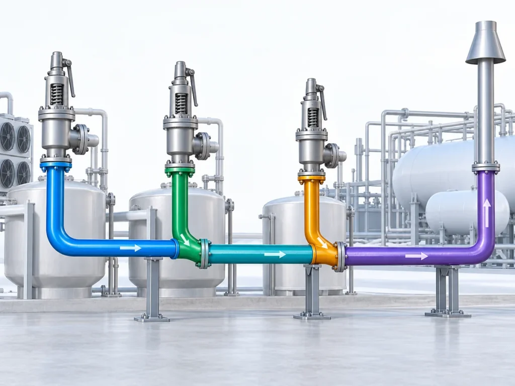
A large external-fire load can place significant demand on the inlet line, outlet line and disposal system. Inlet pressure loss can affect valve performance. Built-up or superimposed back pressure can change the effective operating conditions at the valve. A common relief header may have to handle simultaneous loads if one fire affects several pieces of equipment. Outlet piping, flare or vent-system resistance and the final discharge location must also be consistent with the selected pressure-relief device.
That does not mean this article should become a complete flare-network or back-pressure design guide. The important boundary is simpler: the fire-case load must be carried forward into system verification rather than treated as finished once a valve capacity number has been found.
The fire scenario also does not automatically select a conventional spring-loaded, balanced bellows or pilot-operated configuration. Configuration depends on the actual back pressure, service condition, pressure and temperature, stability requirements, installation and manufacturer limitations. “Fire service” alone is not a valve-configuration decision.
What Must Be Confirmed Before the Fire Case Is Accepted for Design
A useful external-fire analysis should leave a traceable design basis. Before the result is used to select or specify a pressure-relief device, the engineer should be able to answer the following questions.
- What exactly is being protected? Identify the vessel and the relevant design or MAWP basis.
- Why is external fire credible? Define the fire source, equipment exposure and project assumptions.
- What inventory is present? Establish liquid level, fluid composition and phase behavior relevant to the event.
- Which fire method applies? Confirm whether the empirical liquid pool-fire approach is appropriate or whether a different analytical treatment is required.
- What pressure and temperature define the relieving state? Keep operating pressure, set pressure, overpressure/accumulation basis and relieving pressure distinct.
- How was heat input established? Record the wetted/exposed area basis and any environmental, insulation, drainage or other mitigation assumptions.
- How was the required relieving rate calculated? Preserve the thermodynamic basis, including important phase or composition limitations.
- Which standard and edition govern the calculation? Confirm the actual project requirement rather than assuming that every referenced standard is simultaneously applicable.
- Can the selected device demonstrate enough capacity? Use the applicable manufacturer and certification/documentation basis for the selected valve and orifice.
- Can the connected relief system handle the flow? Check inlet losses, back pressure, outlet piping and the disposal system as applicable.
If any of these items is unknown, the uncertainty should remain visible in the engineering review. A missing input should not be replaced by a nominal valve size, a catalogue maximum or a familiar rule of thumb.
Nächster Schritt in der Technik
For an engineering review of an external-fire case, prepare the protected-equipment data, credible fire scenario, process medium and phase, vessel inventory or liquid level, operating and design/MAWP information, set-pressure basis, relieving conditions, fire-exposure assumptions, required relieving load or calculation basis if already available, and the relevant downstream back-pressure or discharge-system information.
That information allows the conversation to begin with the real protection problem rather than with a guessed valve size.
Technische Überprüfung anfordern
To review an external-fire relief case, provide the protected vessel and credible fire scenario, process medium and phase, vessel inventory or liquid level, operating and design/MAWP information, set-pressure basis, relieving conditions, fire-exposure assumptions, required relieving load or calculation basis if available, and relevant back-pressure or discharge-system information. Valve capacity, configuration and final suitability should be confirmed against the selected product data, governing standard and project requirements.
Technische Überprüfung anfordern