تعرّف على سبب عدم كون معيار فقدان الضغط عند المدخل 3% قاعدة قبول أو رفض عامة، وما الذي يحدد مدى انطباقه، وكيفية مراجعة تركيب صمام الأمان عند تجاوزه.

A فقدان ضغط المدخل 3% يُستخدم هذا المعيار على نطاق واسع عند مراجعة تركيبات صمامات تنفيس الضغط، لكنه ليس قاعدة قبول/رفض شاملة لكل صمام أمان أو كل معيار أو كل خدمة.
بموجب API 520 الجزء الثاني، تُعد قيمة 3% المألوفة معيار فرز مهم لفقدان ضغط المدخل غير القابل للاسترداد. وتشير معلومات المعايير الرسمية الصادرة عن API إلى أن الجزء الثاني، الإصدار السابع، هو الإصدار المنشور المستخدم في هذه المقالة، وتذكر أنه قدّم تحليل هندسي لمسار تقييم تركيبات أجهزة تنفيس الضغط.
هذا التمييز يغيّر طريقة استخدام الرقم. لا ينبغي للمهندس أن يبدأ بسؤال: “هل انخفاض الضغط أقل من 3%؟” بل يكون التسلسل الأفضل هو: تحديد الأساس الحاكم، وتأكيد نوع الفقدان الذي يتم حسابه، وتحديد الصمام وتكوين الاستشعار، ثم تحديد ما إذا كان المعيار المألوف هو فعلاً طريقة الفرز المنطبقة.
النتيجة الأقل من 3% لا تضمن بحد ذاتها سلوكًا مستقرًا للصمام. والنتيجة الأعلى من 3% لا تثبت بحد ذاتها أن كل تركيب يجب رفضه. المهم هو الأساس الهندسي الكامن وراء الرقم.
ما يعنيه معيار فقدان المدخل 3% — وما لا يثبته
بموجب API 520 الجزء الثاني، يتعلق المعيار المألوف بإجمالي فقدان الضغط غير القابل للاسترداد بين المعدة المحمية وصمام تنفيس الضغط، منسوبًا إلى ضغط ضبط الصمام.
الكلمة غير قابل للاسترداد أمر مهم. ففقدان ضغط المدخل ليس مجرد كل فرق ضغط قد يوجد بين المعدة المحمية والصمام. فالاحتكاك والاضطراب والتجهيزات والقيود ومقاومات التدفق الأخرى يمكن أن تبدد الضغط أثناء تحرك المائع نحو الصمام. أما تأثيرات الارتفاع والسرعة القابلة للاسترداد فيجب معالجتها وفقًا للطريقة الهيدروليكية المنطبقة بدلاً من تجميعها عشوائيًا في “انخفاض ضغط 3%”.”
يجب أيضًا تحديد أساس التدفق. سعة الصمام المقدرة هي أساس تصميم شائع وفق ممارسات API، لكن ليس صحيحًا كتابة أن كل حساب لفقد المدخل في كل تكوين مسموح به يجب أن يستخدم دائمًا التدفق المقدر. بعض سلوكيات الصمام ومسارات التحليل الهندسي يمكن أن تغيّر الأساس المطبق.
لهذا السبب، فإن عبارة مجردة مثل “فقد المدخل = 2.7%” تكون غير مكتملة ما لم يكن أساس الحساب معروفًا.
| نتيجة الحساب | ما الذي يثبته | ما الذي لا يثبته |
|---|---|---|
| التركيب يحقق معيار فحص فقد المدخل المطبق | تم استيفاء هذا الفحص الهيدروليكي المحدد | تشغيل مستقر مضمون تحت كل ظروف التنفيس |
| التركيب يتجاوز قيمة الفحص المألوفة | مطلوب مراجعة فنية إضافية | حدوث اهتزاز معين أو فشل تلقائي أو رفض عالمي من الكود |
| تحليل هندسي مسموح به يدعم التركيب | قد يكون هناك أساس فني موثق للتركيب المحدد | أن السعة أو الحدود الخاصة بالصمام أو متطلبات المشروع يمكن تجاهلها |
هذا هو التصحيح الرئيسي الأول لقاعدة “3%” الشائعة: النسبة المئوية هي معيار فرز أولي، وليست حدًا فيزيائيًا للاستقرار.
تحتوي صمامات تنفيس الضغط على ديناميكيات نظام لا يمكن لنسبة مئوية واحدة وصفها بالكامل. لذلك، فإن استيفاء معيار الفرز لا ينبغي أن يُترجم إلى “الصمام لا يمكن أن يهتز”، تمامًا كما أن تجاوزه لا ينبغي أن يُترجم إلى “الصمام سوف يهتز”.”
ما الذي يحدد ما إذا كان معيار 3% ينطبق؟
قبل تطبيق أي معيار نسبة مئوية، حدد الجهة التي تحكم التركيب فعليًا.
يمكن أن تؤثر API وASME وISO واللوائح الوطنية ومواصفات المالك وتعليمات المصنع جميعًا على المشروع، لكن ليس لها نفس النطاق أو المكانة.
للحصول على خريطة أوسع لهذه الأدوار، راجع دليل معايير صمامات الأمان. من ZOBAI. بالنسبة للمشاريع التي تستخدم منهجية API تحديدًا، فإن دليل هندسة صمامات الأمان API 520 يوفر سياقًا أوسع لحساب المقاسات والتركيب.
ابدأ بالأساس الحاكم، وليس بالنسبة المئوية
يحدد ASME القسم VIII الفرع 1 من BPVC، إصدار 2025 كالإصدار الحالي المستخدم في هذه المراجعة.
ضمن هيكل BPVC 2025 القسم VIII الفرع 1، تظهر المادة المتعلقة بانخفاض الضغط عند المدخل وذات الصلة بهذا الموضوع في الملحق M غير الإلزامي, ضمن إرشادات التركيب والتشغيل، مع نطاق صريح للجهاز وخدمة الموائع القابلة للانضغاط. ينبغي الحفاظ على هذه الصفة بدلًا من اختصارها إلى “ASME تشترط عالميًا 3%.”
تقدم ISO توضيحًا مختلفًا للمشكلة نفسها. ISO 4126-9 يختص تحديدًا بجزء التطبيق والتركيب من عائلة ISO 4126. ويشمل نطاقه المنشور صمامات الأمان وصمامات الأمان التي تعمل بالبايلوت، وينص على أن معلومات التركيب تفترض تدفق أحادي الطور.
So “the project follows ISO 4126” is still not enough information. The relevant part and service scope matter.
ثم حدد تكوين الجهاز
السؤال التالي هو نوع جهاز تنفيس الضغط المركّب.
لا يتبع الصمام التقليدي المحمّل بنابض مباشر، والتصميم المتوازن، وصمام الأمان الذي يعمل بالبايلوت بالضرورة المنطق نفسه في الاستقرار أو الاستشعار. وفي الصمام الذي يعمل بالبايلوت، قد يكون الموقع الذي يستشعر منه البايلوت ضغط النظام المحمي ذا أهمية خاصة.
وهذا لا يعني أن “التشغيل بالبايلوت = إعفاء من قاعدة 3%”. التمييز الصحيح أضيق من ذلك: a specific sensing arrangement may change how inlet pressure loss affects valve control, while the main inlet hydraulics can still affect available relieving pressure and capacity.
Readers who need the operating distinction first can use the separate pilot-operated safety valve working-principle guide rather than expanding this article into a complete pilot-valve tutorial.
Confirm service and relief duty
The governing route can also depend on what the device is protecting against.
A narrowly defined liquid thermal-expansion duty should not automatically be generalized to process heating, vaporization, fire exposure, blocked outlet, or another credible overpressure scenario. Likewise, a single-phase installation basis should not be assumed to cover a two-phase relieving condition without checking the appropriate standard basis.
ISO makes that scope boundary clear: Part 9 states that its installation information assumes single-phase flow, while ISO 4126-10:2024 separately addresses safety-valve and bursting-disc sizing for gas/liquid two-phase flow.
The practical sequence is:
governing basis → device and sensing configuration → service and relief duty → calculation basis → applicable inlet-loss criterion.
The percentage comes after those questions.
Why Inlet Pressure Loss Can Affect Safety-Valve Stability
The reason inlet pressure loss matters becomes clearer once the valve starts flowing.
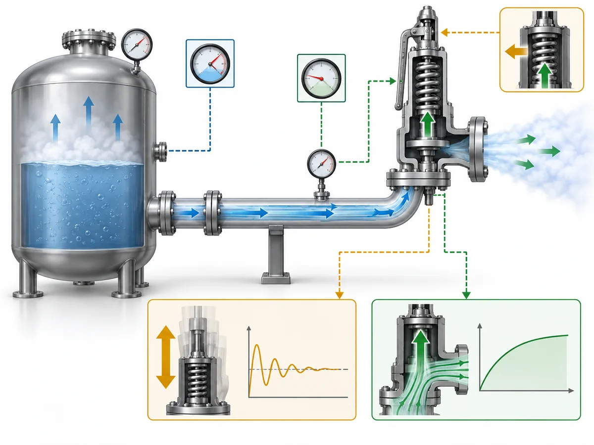
Before a relief event, the pressure at the protected system and the valve inlet may be relatively close, apart from relevant static effects. Once substantial relieving flow develops, friction and turbulence in the inlet path create nonrecoverable pressure loss.
The valve can then experience a lower inlet pressure than the protected equipment.
For a direct spring-loaded valve, that change can interact with the force balance that controls opening, lift, and reseating. A simplified sequence is:
protected-system pressure rises → valve opens → relieving flow increases → inlet losses increase → valve-inlet pressure changes → valve response changes → flow changes again.
Under unfavorable combinations of piping and valve behavior, this feedback can contribute to unstable operation.
It is still incorrect to convert that mechanism into “above 3%, the valve chatters.” Inlet pressure loss is only one part of the system. Valve characteristics, relief demand, outlet back pressure, sizing, and dynamic or acoustic interactions can also influence stability.
Outlet back pressure is a separate engineering variable from inlet pressure loss. Readers investigating the downstream side should use the dedicated Back Pressure in Spring Loaded Safety Valves guide instead of combining the two calculations.
Inlet loss also creates a second issue that should not disappear inside the chatter discussion: relieving capacity.
Nonrecoverable pressure loss reduces the pressure available at the relief-valve inlet during flow. Where that effect is material, the capacity consequence must be checked separately.
That gives the engineer two different questions:
Is the valve/system expected to operate stably?
Can the installed valve still deliver the required relieving capacity at the actual inlet conditions?
Passing one check does not automatically answer the other.
When the Familiar 3% Criterion Is Not the Whole Decision
“Not universal” does not mean “3% can be ignored.” It means recognized engineering frameworks contain scope-dependent cases where a simple comparison against the familiar screening value does not complete the decision.
A specific installation may require documented engineering analysis
API’s official information on API 520 الجزء الثاني، الإصدار السابع confirms that the published edition introduced an Engineering Analysis for evaluating pressure-relieving-device installations.
Within API 520 Part II, that installation-specific route can extend beyond a single friction-loss percentage and, where applicable, consider capacity effects, valve behavior, force balance, system response, operating history, or dynamic interaction.
This should not be presented as an “exception that lets engineers ignore 3%.” The analysis exists to determine whether the specific installation has a defensible technical basis.
Known unstable behavior changes that decision. Under the API 520 Part II engineering-analysis framework used here, an existing installation with credible chatter evidence should not simply be reclassified as acceptable because a later calculation can be produced.
Narrow thermal-expansion service requires a narrow interpretation
API 520 Part II also treats a narrowly bounded case involving liquid hydraulic expansion caused solely by ambient heating differently from the general inlet-loss screening path.
الكلمة solely is critical.
The same treatment must not be silently expanded to every blocked-in liquid line, every thermal-relief valve, process heating that may vaporize the liquid, or a system with another credible overpressure scenario.
If the duty no longer fits that narrow basis, the ordinary inlet-loss assessment has to be revisited.
Remote sensing changes the question, not the laws of hydraulics
API 520 Part II gives specific treatment to a remotely sensed pilot-operated pressure relief valve. In that arrangement, the pilot can sense pressure at a location selected to represent protected-system pressure rather than relying only on the pressure at the main valve inlet.
That can alter the relationship between main-inlet pressure loss and pilot control.
It does يحدد mean the pressure loss in the main inlet disappears. The main valve still has to pass the required relieving flow, so available inlet pressure and capacity remain relevant.
The sensing line itself also becomes part of the review. Its location, pressure losses, and compatibility with the chosen pilot design may require manufacturer-specific information.
Flow regime can change the standards basis
ISO 4126-9 states that its installation information assumes single-phase discharge, while ISO 4126-10:2024 deals with gas/liquid two-phase sizing.
That supports a scope boundary, not an invented second “two-phase 3% rule.”
If the relieving condition is two-phase, the correct action is to verify the applicable method—not to transfer a single-phase rule unchanged or invent an alternative percentage.
Across these examples, the engineering principle is consistent: do not search for an exception to 3%; identify the actual governing route for the device, duty, sensing arrangement, and installation.
How to Review an Installation Above the Familiar Criterion
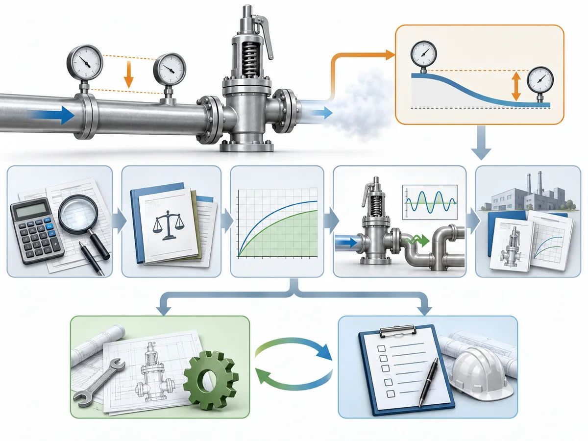
An inlet-loss result above the familiar screening value is a reason to investigate. It is not enough information to approve or reject the installation.
1. Verify that the pressure-loss calculation is comparable with the criterion
Check the calculation boundary, inlet pipe geometry, fittings, reducers, restrictions, fluid properties, relief phase, and any upstream device that contributes hydraulic resistance.
A technically correct pressure-drop calculation can still be the wrong comparison if it uses a different pressure quantity or boundary from the governing criterion.
For broader installation geometry and piping considerations, see the دليل تركيب صمام الأمان.
2. State the flow basis explicitly
Confirm whether the calculation uses rated capacity, required relieving flow, or another basis permitted for the actual device and assessment method.
Do not hide the assumption inside the hydraulic software or calculation sheet. It is one of the inputs that can materially change the reported loss.
3. Check relieving capacity separately
If inlet loss is significant, determine whether the installed inlet pressure changes the available relieving capacity.
If the real question is orifice and certified capacity rather than inlet piping alone, route that work to the دليل حساب مقاسات صمامات الأمان وسعة التنفيس المعتمدة.
A stability assessment is not a substitute for this capacity check.
4. Confirm the valve architecture and sensing arrangement
Identify whether the device is conventional spring-loaded, balanced, pilot-operated, locally sensed, or remotely sensed.
Where an advanced assessment depends on opening, closing, or pilot characteristics, generic valve-type descriptions are not enough. Device-specific manufacturer information may be required.
5. Treat operating history as evidence—not proof of every future case
For an existing installation, useful records can include actual lift events, inspection findings, repair history, and evidence of damaged seats, guides, internals, or associated piping.
But “we have never seen chatter” is not the same as demonstrating that the system has successfully experienced the governing relief condition.
Conversely, credible evidence that the valve has chattered should materially change the decision. That condition deserves investigation and correction, not a paper justification based solely on a later calculation.
6. Determine whether a recognized engineering-analysis route applies
Where the governing framework permits it, a documented analysis can examine the actual installation rather than relying on the default screening value alone.
Depending on the method, that can require capacity correction, valve characteristics, force balance, pressure response, acoustic considerations, or operating evidence.
The purpose is not to find a mathematical way around the rule. It is to answer a narrower question: Can this particular device and installation be shown to satisfy the applicable engineering basis?
7. Change the installation when the evidence does not support it
Physical modification remains a valid—and sometimes necessary—outcome.
Depending on the cause, the engineering response may involve reducing inlet length, removing avoidable restrictions, using lower-resistance fittings, increasing inlet diameter, better matching the selected relieving capacity to the required load, changing the protection arrangement, or evaluating a different valve/sensing architecture.
Those are options, not a universal repair recipe.
An exceedance should therefore lead to verify → classify → assess → redesign if necessary, rather than “3.1% → automatic failure” or “engineering analysis → automatic acceptance.”
What to Document for Engineering Review or RFQ
An engineer or valve supplier cannot evaluate an inlet-pressure-loss concern reliably from valve size and set pressure alone.
The review package should describe the protected system and the calculation that produced the concern.
| المعلومات المطلوب تقديمها | Why it affects the inlet-loss review |
|---|---|
| Protected equipment / pressure boundary | Defines where the inlet path begins |
| Governing code, standard, and project specification | Determines the applicable assessment basis |
| سيناريو تنفيس موثوق | Defines the duty being reviewed |
| أساس ضغط الضبط | Required to interpret percentage-based criteria |
| معدل التنفيس المطلوب | Defines the required protection duty |
| Flow rate used in the inlet-loss calculation | Reveals whether the hydraulic basis matches the selected method |
| Fluid and relieving phase | Affects hydraulics and standards scope |
| Inlet piping layout / isometric | Shows line length, elevation, routing, and restrictions |
| Pipe sizes, reducers, fittings, and valves | Establish the sources of nonrecoverable loss |
| Rupture disk or other upstream device, if present | May add hydraulic resistance |
| Calculated inlet pressure loss and calculation method | Shows the result and how it was obtained |
| Relief-valve architecture | Affects the applicable stability or analysis route |
| Pilot sensing arrangement, where applicable | Can change how protected-system pressure is sensed |
| Device-specific operating data required by the selected analysis | Prevents generic assumptions about actual valve behavior |
| Lift, inspection, and repair history for an existing installation | May reveal evidence relevant to stability assessment |
This is also where general technical guidance ends and product-specific evidence begins.
A public article can explain the inlet-loss decision process. It cannot establish the dynamic behavior, remote-sensing arrangement, stability limit, allowable inlet pressure loss, or advanced-analysis data for a specific safety valve model unless those facts are documented for that model.
So a supplier inquiry should not stop at: “Can your valve work with more than 3% inlet pressure drop?”
A technically useful inquiry provides the relief duty, applicable standard, hydraulic calculation, valve configuration, and unresolved engineering question.