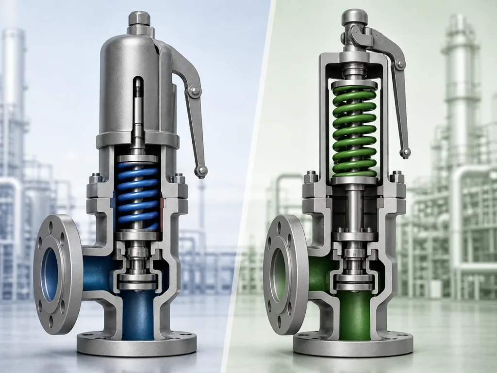
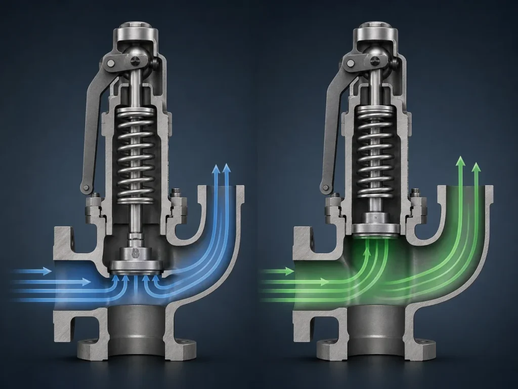
直接回答:公共排放总管使安全阀出口压力成为系统结果,而非单阀输入。审查必须确定可信的泄放工况,识别哪些装置可能同时参与泄放,区分预先存在的叠加背压与泄放流量产生的背压,追踪支管和共用排放管路的阻力,并确定……

直接回答: 公共排放总管使安全阀出口压力成为系统结果,而非单阀输入。审查必须确定可信的泄放工况,识别哪些设备可能同时参与泄放,区分预先存在的叠加背压与泄放流量产生的背压,追踪支管和共用排放管道的阻力,并确定这些相互作用何时需要针对项目的专项水力分析。物理连接本身并不定义同时泄放,单个阀门的数据也无法确定整个共用总管中的压力状况。.
本指南仅负责该系统性决策。阀门背压行为的详细说明、单阀定径与认证排量、一般安全阀选型以及更广泛的 API 521 泄放系统方法论,仍由各自的专门页面负责。.
为什么公共排放总管会改变泄压阀问题
具有独立排放通道的安全阀,可以对照分配给该通道的下游工况进行校验。当多个压力泄放装置向相互连通的下游管道排放时,这一假设发生变化:某一出口处的压力可能取决于共享系统中其他位置的情况。.
从独立出口管道到耦合下游系统
在本指南中, 公共排放总管 是指可接收来自多个压力泄放装置泄放流量的相互连接的下游管道。这是一个实际的系统描述,并非声称该术语具有统一的通用标准定义。.
TSASK发布的公共集管指南 明确涉及通过公共集管与其他泄压装置互连的压力泄放装置排放管道。在该监管范围内,关键点很明确:互连的出口必须作为一个系统来审查,而不是作为无关的排放管线。.
工程后果是耦合。一个支管在分析上并不终止于阀门出口喷嘴;它汇入一个下游路径,该路径也可能承载来自其他连接源头的流量或压力。因此,阀门所看到的出口条件可能取决于其局部支管、集管的公共段、下游压力源以及正在评估的泄放工况。.
一个阀门的排放如何改变另一个阀门的出口条件
Baker Hughes工程指南 指出连接到公共集管的其他泄压阀可能是可变叠加背压的来源。它还指出,公共集管压力可能根据哪个装置或装置组合在排放而变化。.
这并不证明假设每个连接点都承受相同的压力,或者一个泄压阀会在网络中的任何地方产生可预测的压力上升。这意味着共享的压力条件是系统结果。.
因此,一个实际的诊断问题是:
- 如果另一个泄压装置开始排放,这个阀门出口处的下游压力条件是否会改变?
- 如果是,则不能仅根据该阀门的独立出口数据来审查它。.
- 必须首先为相关泄放工况确定系统条件,然后将其传递回单个阀门检查。.

Which Safety Valves Belong in the Same Simultaneous-Relief Case?
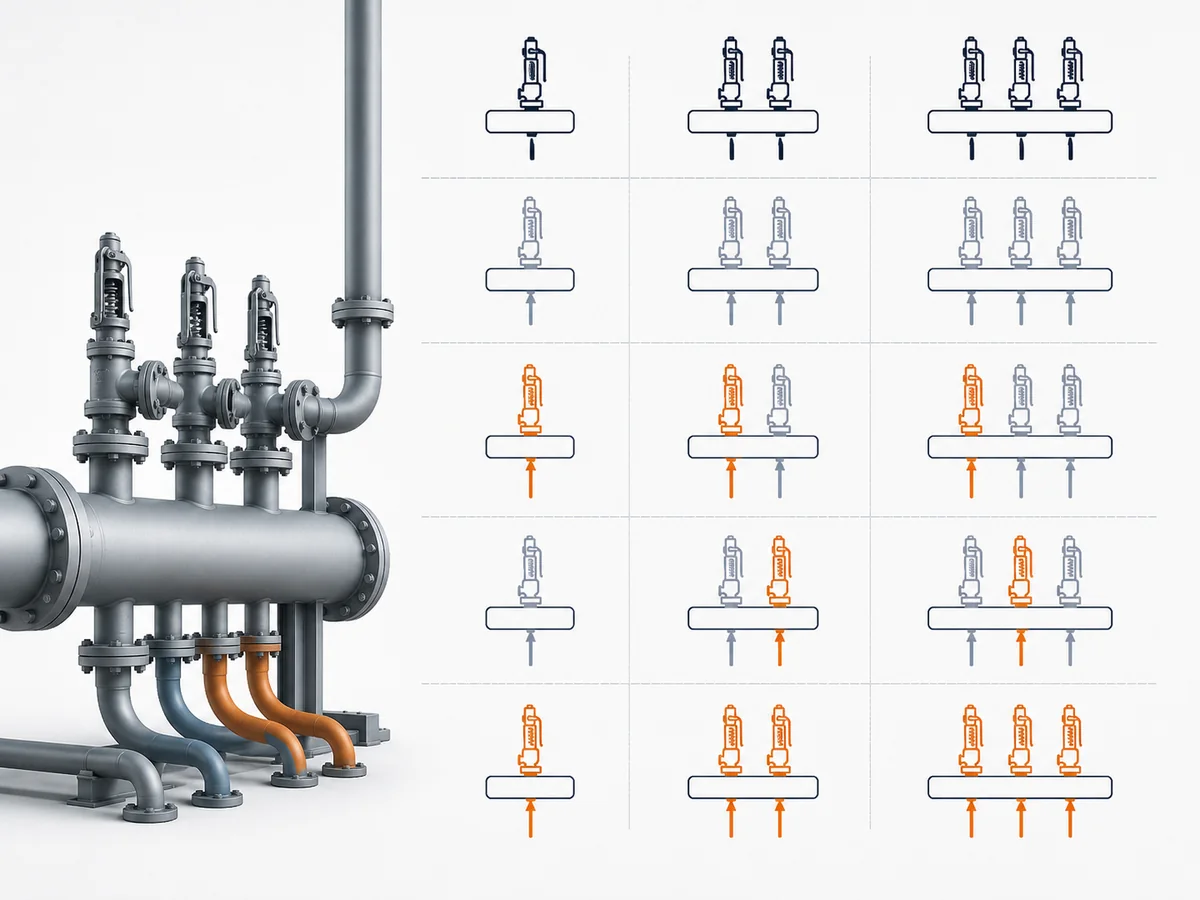
Connection to the same header establishes hydraulic interaction potential; it does not, by itself, establish concurrency. The simultaneous-relief case must be built from the relief scenario and the devices that can credibly contribute under that scenario.
Start With the Credible Initiating Event
The first decision is not how many valves appear on the discharge network. It is what event or design case is being evaluated. Only then can the engineer identify which connected pressure-relief devices are credible contributors to that case.
The broader methodology for establishing relief scenarios belongs to the API 521 pressure-relief systems guide. For this article, the system-level requirement is narrower: the common-header calculation or review must use a defined relief case rather than an undefined collection of connected valves.
Separate Concurrent Contributors From Merely Connected Valves
TSASK’s common-header guidance provides a useful scoped example. It recognizes that more than one pressure-relief device may be relieving and refers to clearly identified relieving devices. In its fire-case discussion, it also calls for engineering judgement about whether additional relief valves would realistically relieve.
That jurisdiction-specific guidance should not be converted into a universal concurrency rule. The transferable engineering logic is this:
- Define the relief case.
- List the devices connected to the relevant common discharge system.
- Identify which of those devices can credibly contribute in that case.
- Exclude a device from that case only because the project relief basis supports the exclusion, not simply because including it is inconvenient.
- Carry the resulting contributor set into the common-header review.
Why “Add Every Valve” Is Not a Universal Rule
Automatically summing every connected valve is not supported as a universal rule by the frozen evidence. Neither is the opposite shortcut of assuming only one valve matters.
A useful red-team check is to challenge both extremes:
| Assumption | Question that must be answered | Action if the answer is unknown |
|---|---|---|
| Only one connected valve can relieve | What project relief scenario proves the other connected devices are not credible contributors? | Keep the concurrency question open. |
| Every connected valve relieves simultaneously | What common initiating event or project basis makes all of them credible contributors? | Do not treat physical connection alone as proof. |
| A previous header case is still governing | Does the current scenario have the same contributor set and downstream condition? | Re-establish the case before reusing the result. |
The hydraulic flow basis for those contributors must come from the applicable project relief-system design basis. No single required, rated or certified-capacity basis is prescribed here as universally correct.
How to Review a Combined Discharge Case Without Confusing It With Valve Sizing
Once the credible contributors have been identified, the purpose of the common-header review is to establish the downstream condition produced by that case. It is not yet a valve-type decision and it does not replace individual safety-valve sizing.
Confirm the Applicable Project Flow Basis
The contributor set comes from the defined relief case. The hydraulic input basis for those contributors must then be confirmed from the project’s governing relief-system design basis.
Required relieving rate, rated capacity and certified capacity are not terms that can simply be substituted for one another, and the frozen evidence does not establish any one of them as the universal common-header hydraulic basis.
Individual relief-load sizing, orifice selection and certified-capacity verification remain with the safety-valve sizing and certified relieving capacity guide.
Trace Branch Paths, Shared Resistance and the Downstream Boundary
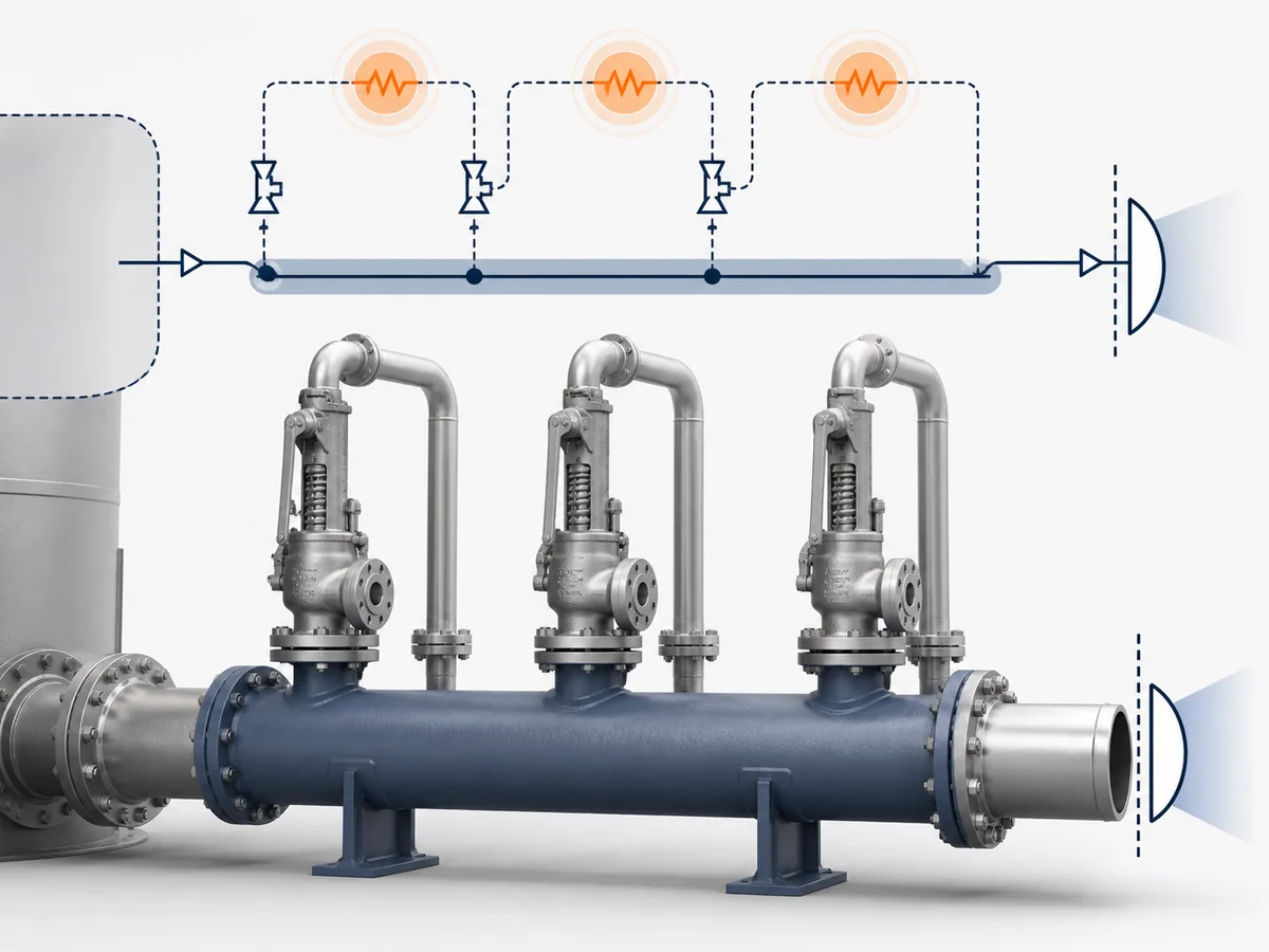
The next task is to map where each credible contributor’s discharge travels. The review should distinguish three system elements:
- Local branch path: the downstream path specific to one relief device before it joins shared piping.
- Shared discharge path: the portion of the downstream network through which flow from more than one credible contributor can pass.
- Downstream boundary or pressure source: the external system condition that can impose pressure back into the relief network.
ISO 4126-7 supports the basic causal distinction: built-up back pressure results from flow through the valve and discharge system, while superimposed back pressure originates from other pressure sources in that system.
This branch-versus-shared distinction is important because a valve can be affected by both its own discharge path and pressure generated elsewhere in the connected network. Treating the entire outlet system as one undifferentiated resistance can hide where the interaction comes from.
Determine the Outlet Pressure Condition Relevant to Each Valve
The system-level result that matters to the individual valve review is the outlet-pressure condition applicable at that valve connection for the relief case being considered.
A practical review sequence is:
- freeze the relief case;
- freeze the credible contributor set;
- confirm the hydraulic flow basis required by the project;
- trace each contributor through its local branch and the shared discharge path;
- include the applicable downstream pressure boundary or other pressure sources;
- establish the outlet condition relevant to each valve connection; and
- only then compare that condition with the applicable valve-specific requirements.
Different connection points should not be assumed to have identical conditions unless the project analysis establishes that assumption.
Keep Individual Capacity and Valve-Type Checks With Their Existing Owners
Common-header adequacy and individual valve adequacy are related, but they are not the same decision.
The sizing and certified capacity guide owns the individual capacity path. The general safety-valve selection guide owns valve-type and application selection. The 背压与波纹管指南 owns the detailed effect of an established back-pressure condition on valve design.
This page stops one step earlier: it helps determine what downstream condition those individual checks must use.
When a Common Header Requires Project-Specific Hydraulic Analysis
Qualitative screening should stop when the required outlet condition depends on scenario-specific combined flow through the actual interconnected discharge network and cannot otherwise be established. The presence of multiple credible contributors alone is not the trigger; the trigger is whether their combined discharge affects the shared outlet condition in a way that must be resolved from the project hydraulics.
Conditions That Defeat a Qualitative Header Check
Project-specific hydraulic analysis is needed when the required outlet condition depends on one or more unresolved system interactions such as:
- multiple credible contributors whose combined discharge changes the shared outlet condition in a way that must be resolved from the interconnected network;
- pressure at one outlet that changes according to which other relief sources are active;
- local branch paths and common downstream resistance that both affect the resulting condition;
- a downstream pressure boundary that changes with the operating or relief case; or
- a flow regime outside the single-phase boundary used for the ordinary discussion in this guide.
These are decision triggers, not design limits. They do not define an allowable back-pressure percentage, a minimum header size or a universal acceptance rule.
Why Different Relief Cases Can Produce Different Header Pressure Profiles
Baker Hughes工程指南 notes that common-header pressure can vary with the device or combination of devices venting. That creates a useful troubleshooting rule: if two relief cases have different contributor sets or different downstream conditions, do not assume that a header-pressure result from one case automatically represents the other.
Likewise, the case with the most valves is not automatically the governing case merely because its contributor count is larger. The governing result is project-specific and depends on the actual case and network.
Two-Phase or Flashing Conditions as an Escalation Boundary
ISO 4126-9 states that its application and installation information assumes single-phase discharge and directs two-phase applications to separate treatment. ISO 4126-7 likewise routes flashing-liquid and two-phase conditions away from its ordinary treatment.
That establishes a firm scope boundary for this article: if flashing or two-phase behavior is possible, do not extend the qualitative single-phase reasoning here into a hydraulic conclusion. The applicable specialist method and project analysis must take over.
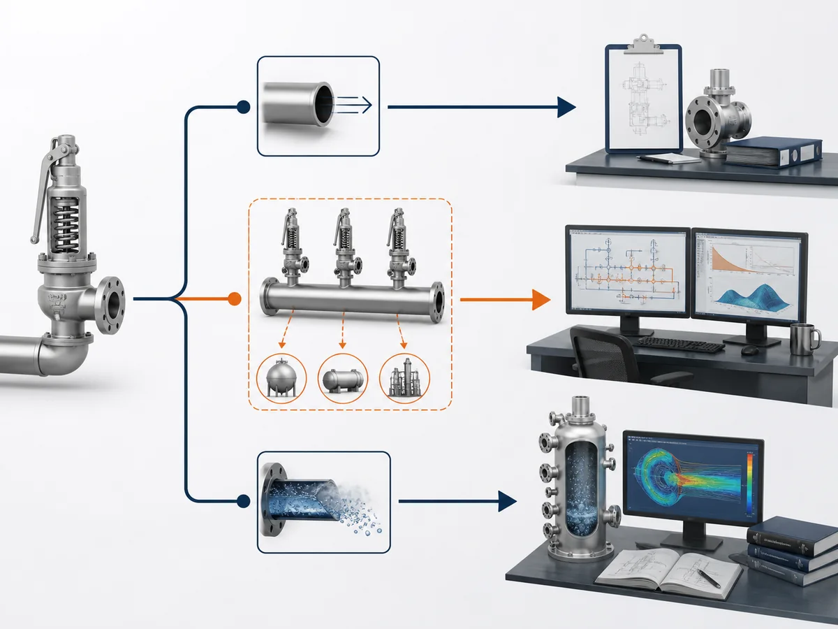
What Project Data Must Be Defined Before the Header Can Be Accepted
The final question is not “What generic rule says this header is acceptable?” It is “Do we have enough project information to establish the actual downstream condition for the applicable relief cases?”
Relief Scenario and Simultaneous-Contributor Inputs
Before the common-header condition can be resolved, confirm:
- the relief scenario or initiating event being evaluated;
- the connected pressure-relief devices relevant to that system;
- which of those devices are credible simultaneous contributors in the defined case;
- the hydraulic flow basis required by the governing project relief-system design basis; and
- the applicable project code, jurisdiction and design criteria.
If the contributor set or hydraulic flow basis is still being guessed, the common-header review is not ready for a final adequacy conclusion.
Fluid, Relieving Conditions, Header Network and Downstream Boundary Inputs
The project analysis must also have the system information required by its applicable hydraulic method. At article level, the essential data categories are:
- fluid phase and whether flashing or two-phase behavior is possible;
- the relieving-condition and fluid-property inputs required by the selected method;
- the outlet branches and common-header arrangement;
- the geometry and resistance-producing features required by the hydraulic model;
- the relevant branch connection or tie-in locations; and
- the downstream pressure boundary and other connected pressure sources.
These categories are deliberately qualitative. Actual line dimensions, flow rates, pressures, temperatures and resistance values must come from the project rather than from a generic article.
Valve-Specific Limits Are Checked After the System Condition Is Known
Once the project system analysis has established the outlet condition applicable to a valve, that condition can be checked against the relevant manufacturer and project requirements for the selected device.
The sequence should therefore remain:
- define the relief case;
- identify credible simultaneous contributors;
- establish the shared-system outlet condition;
- then perform the individual valve sizing, back-pressure and selection checks owned by the relevant technical guides.
Selecting a different valve construction does not remove the need to establish the shared-system condition first. Detailed back-pressure behavior remains with the 背压与波纹管指南, while complete device selection remains with the general selection guide.