Review LPG safety valve discharge piping, flare vs vent routing, superimposed and built-up back pressure, outlet checks, and the data needed for an RFQ.

An LPG safety valve is not fully reviewed when its set pressure and relieving capacity have been established. The outlet still has to discharge into a defined system, and that downstream system can change the pressure acting on the valve during relief.
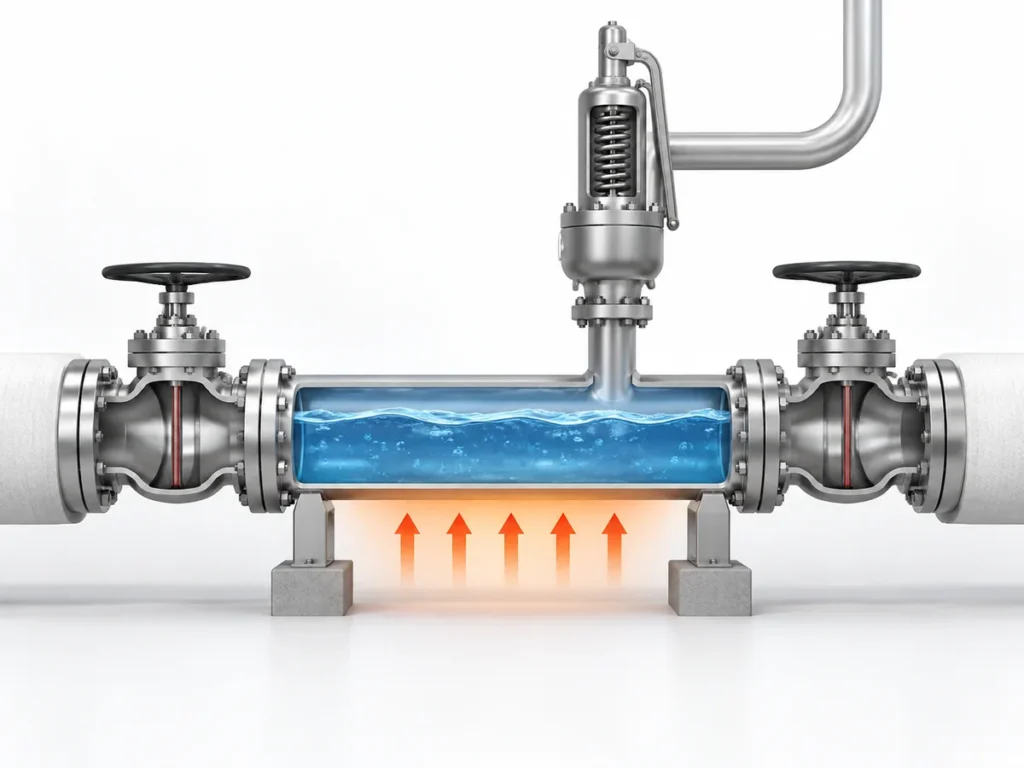
For an LPG installation, three questions should therefore be resolved together: Where will the relief stream go? What back pressure will exist before and during relief? And can the selected valve operate within its documented limits when connected to that outlet system?
A flare, atmospheric vent, closed recovery system or other disposal route should not be selected from a generic rule about LPG. The protected equipment, relief scenario, fluid state, site arrangement, applicable jurisdiction and project design basis all affect that decision. Once the destination is established, the discharge piping and downstream pressure profile become part of the valve review.
For broader LPG product-family context, see ZOBAI’s LPG Safety Valves page. This page stays narrower: it deals with the discharge-system interface, not complete valve sizing or product selection.
Where Should an LPG Safety Valve Discharge: Flare, Vent or Another Disposal System?
There is no single global rule that every LPG safety valve must discharge to a flare. There is equally no general rule that atmospheric discharge is acceptable merely because the outlet terminates outdoors.
The destination has to come from the applicable installation and relief-system design basis.
For example, U.S. OSHA requirements for particular covered LP-Gas installations explicitly address relief discharge to the open air, discharge-line arrangement and, in some cases, common headers or condensate provisions. Those requirements are installation-specific; they are not a universal permission for atmospheric venting. OSHA 29 CFR 1910.110
UK HSE relief-system guidance takes a broader system view: relief discharge should pass to an appropriate safe location, which may include the atmosphere, a knockout drum, scrubber, incinerator, flare stack or another suitable destination depending on the hazard and installation. HSE also treats the design basis of the relief stream as something that should be documented. HSE relief-system guidance
| Вопрос | Что он устанавливает |
|---|---|
| Какое оборудование защищается? | The pressure boundary and installation context |
| What credible event causes relief? | The governing relief case |
| What is the LPG state during relief? | The actual fluid entering the discharge system |
| What project, jurisdiction and design basis apply? | The allowed relief/disposal approach |
| Is the destination atmosphere, flare, closed recovery or another engineered system? | The downstream boundary |
| Does that destination impose pressure at the valve outlet? | The back-pressure review that follows |
A flare may be the correct destination for one LPG relief duty and not another. An atmospheric route may be specifically addressed for a different installation. Neither “LPG is flammable, so use a flare” nor “outdoors means venting is acceptable” is a sufficient engineering basis.
If the approved disposal destination is still unresolved, the valve-system review is not ready to close. In this page’s decision framework, that condition is treated as an engineering ОСТАНОВИТЬ; HOLD is a screening label used here, not a regulatory or code classification.
What Back Pressure Must Be Defined Before the Outlet System Can Be Reviewed?
“Back pressure” is not sufficiently precise as a single RFQ entry.
The first distinction is between наложенное противодавление и возникающее противодавление.
Наложенное противодавление exists at the valve outlet before that valve opens. In a closed or common header, it may be relatively constant or it may vary as the downstream system changes.
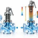
Накопленное противодавление develops after the valve opens because the relief flow passes through the outlet pipe, fittings, header and other downstream resistance.
Baker Hughes Consolidated pressure-relief documentation uses this same distinction between pressure already present downstream before the valve opens and pressure developed by relieving flow through the discharge system. Baker Hughes back-pressure technical guidance
During a relieving event, the engineer therefore needs to understand the complete outlet-pressure condition, not merely one unqualified number.
| Входное противодавление | Инженерный вопрос |
|---|---|
| Наложенное противодавление | What pressure exists at the valve outlet before this device opens? |
| Minimum / normal / maximum condition | What range can exist in service? |
| Постоянное или переменное | Can the pre-existing pressure change with downstream operation? |
| Накопленное противодавление | What pressure develops because the valve is relieving? |
| Нормативное условие сброса | At what relief flow was that value established? |
| Outlet pressure during relief | What condition will the selected valve actually experience? |
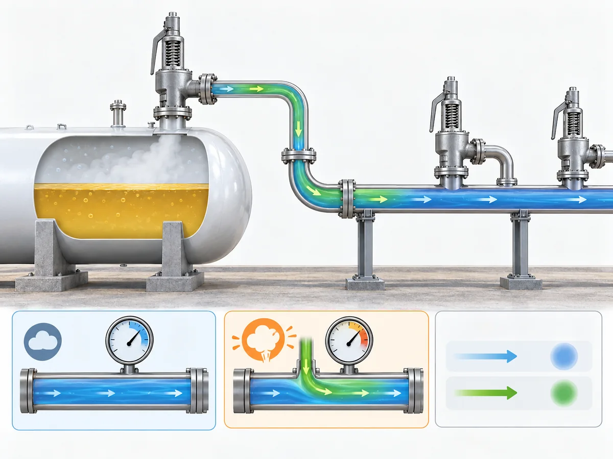
This becomes especially important with a flare or common closed header. Other equipment can influence the pressure already present in the downstream system, while the current valve’s own relieving flow adds another hydraulic contribution.
A supplier therefore gains little from an unqualified entry such as:
Back pressure: 2 bar
That entry does not identify whether the pressure exists before relief, develops during relief, varies with other equipment, or represents the governing outlet condition.
A better handoff separates:
- the expected superimposed back-pressure range;
- whether that pressure is constant or variable;
- the built-up back pressure for the governing relief case;
- the downstream calculation or system basis used to establish those conditions.
For a deeper explanation of superimposed, built-up and total back pressure—and the limits of balanced-bellows designs—use ZOBAI’s Back Pressure and Bellows engineering guide.
One shortcut should be avoided: using a single generic percentage as the universal allowable back-pressure limit. Published limits depend on valve design, model, service and manufacturer documentation. No cross-industry percentage rule is used here.
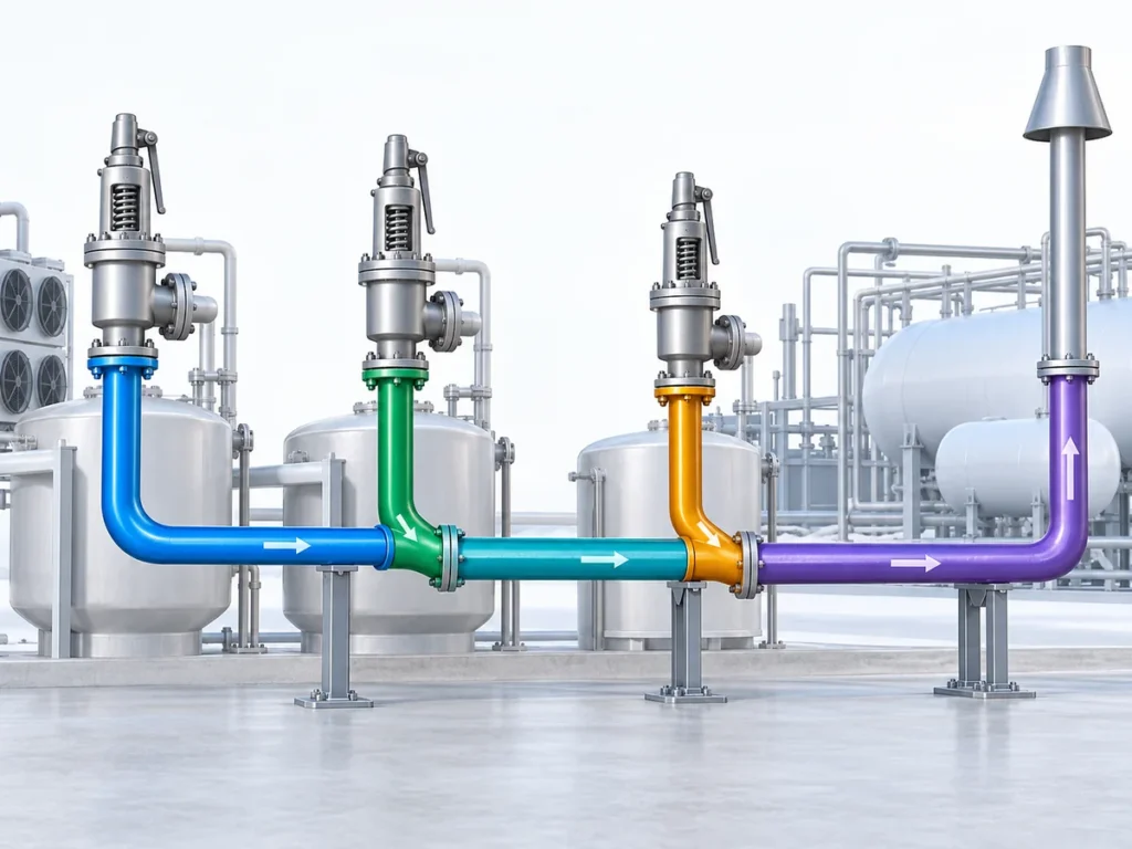
How Do Discharge Piping and a Common Header Affect the Safety Valve?
When an LPG safety valve opens, the relieving fluid still has to travel through a physical flow path.
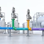
That path can include a tailpipe, elbows, reducers, long horizontal or vertical runs, a common header and the final disposal system. Resistance through that route contributes to the pressure at the valve outlet.
The basic engineering chain is:
relieving flow → downstream resistance → outlet pressure → back pressure at the safety valve
HSE specifically identifies back pressure as a factor that can affect relief-valve opening and closing pressure, stability and capacity. HSE relief-system guidance
A shared header adds another layer. The condition at one valve outlet can depend on what is happening elsewhere in the disposal network. That does предписывает mean every connected device should automatically be assumed to relieve simultaneously. It means the project must define the applicable common-header or simultaneous-relief basis.
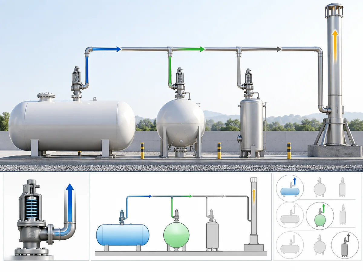
This separates two engineering tasks that are often mixed together.
Valve sizing asks: can the pressure-relief device provide the required relieving capacity under the applicable sizing basis?
Installed discharge review asks: what outlet pressure and mechanical conditions will exist when that flow passes through the actual downstream system?
The first does not automatically close the second.
API describes Part II of API 520 as the installation part of its pressure-relieving-device practice and specifically notes engineering analysis for appropriate PRD installation. API 520 Part II information
For a valve tied into a common flare header, asking only for normal flare-header pressure is not enough.
What outlet-pressure profile will this valve experience before and during the governing relief event under the project’s applicable header scenario?
ZOBAI High Back Pressure application page provides broader application context; this page remains focused on the LPG discharge interface.
When Does Back Pressure Change the Valve-Configuration Review?
Back pressure becomes a valve-configuration issue when the documented behavior or limits of the candidate have to be checked against the actual downstream-pressure profile.
That review should begin with the outlet conditions, not with a predetermined valve type.
| Candidate design | What the engineer should verify |
|---|---|
| Пружинный клапан | How actual superimposed and built-up back pressure affect the candidate’s documented operating and capacity limits |
| Balanced-bellows valve | What back-pressure effect the balancing element addresses, plus the bellows, bonnet and model-specific limits |
| Клапан с пилотным управлением | Whether the specific pilot, sensing and exhaust arrangement is appropriate for the downstream system |
Emerson/Crosby pressure-relief engineering material treats conventional and balanced constructions according to their actual design and operating limits rather than as interchangeable categories, while Anderson Greenwood pilot documentation makes pilot venting and closed-header configuration design-specific. These sources support a candidate-by-candidate review rather than a universal architecture rule. Emerson pressure-relief engineering handbook
A conventional valve is not automatically unacceptable because some back pressure exists.
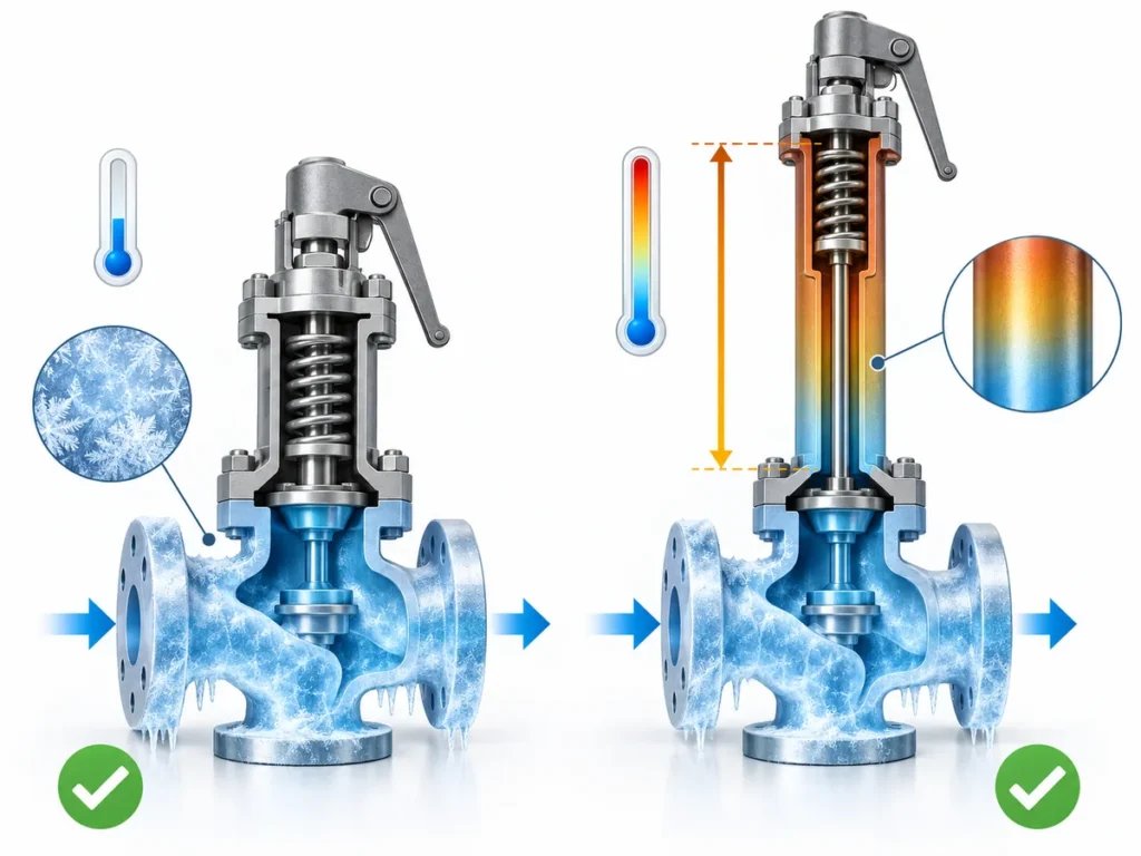
Likewise, a balanced-bellows valve should not be treated as “back-pressure proof.” Balanced construction can reduce specific outlet-pressure force effects, but the valve still has model limits and the downstream system still determines the pressure applied at the outlet.
Pilot-operated valves require the same discipline. Some pilot designs can be suitable for closed-header or back-pressure service, but the pilot architecture, sensing arrangement and exhaust route matter. “Pilot operated” is not evidence of unlimited back-pressure capability.
A defensible screening sequence is:
- define the downstream-pressure profile;
- separate superimposed from built-up conditions;
- identify whether the condition is constant or variable;
- screen candidate valve architectures;
- verify the actual manufacturer’s limits for the selected model;
- retain a separate review of the outlet piping and header.
A common procurement shortcut is:
high back pressure = balanced bellows.
That shortcut is not sufficient. A balanced design may be appropriate. A suitable pilot-operated design may be worth evaluating. A conventional valve may remain acceptable under its documented conditions. Without the actual relief duty, downstream-pressure profile and manufacturer evidence, these architectures should not be ranked as universally better or worse.
What Should Be Checked in the LPG Safety-Valve Outlet Piping?
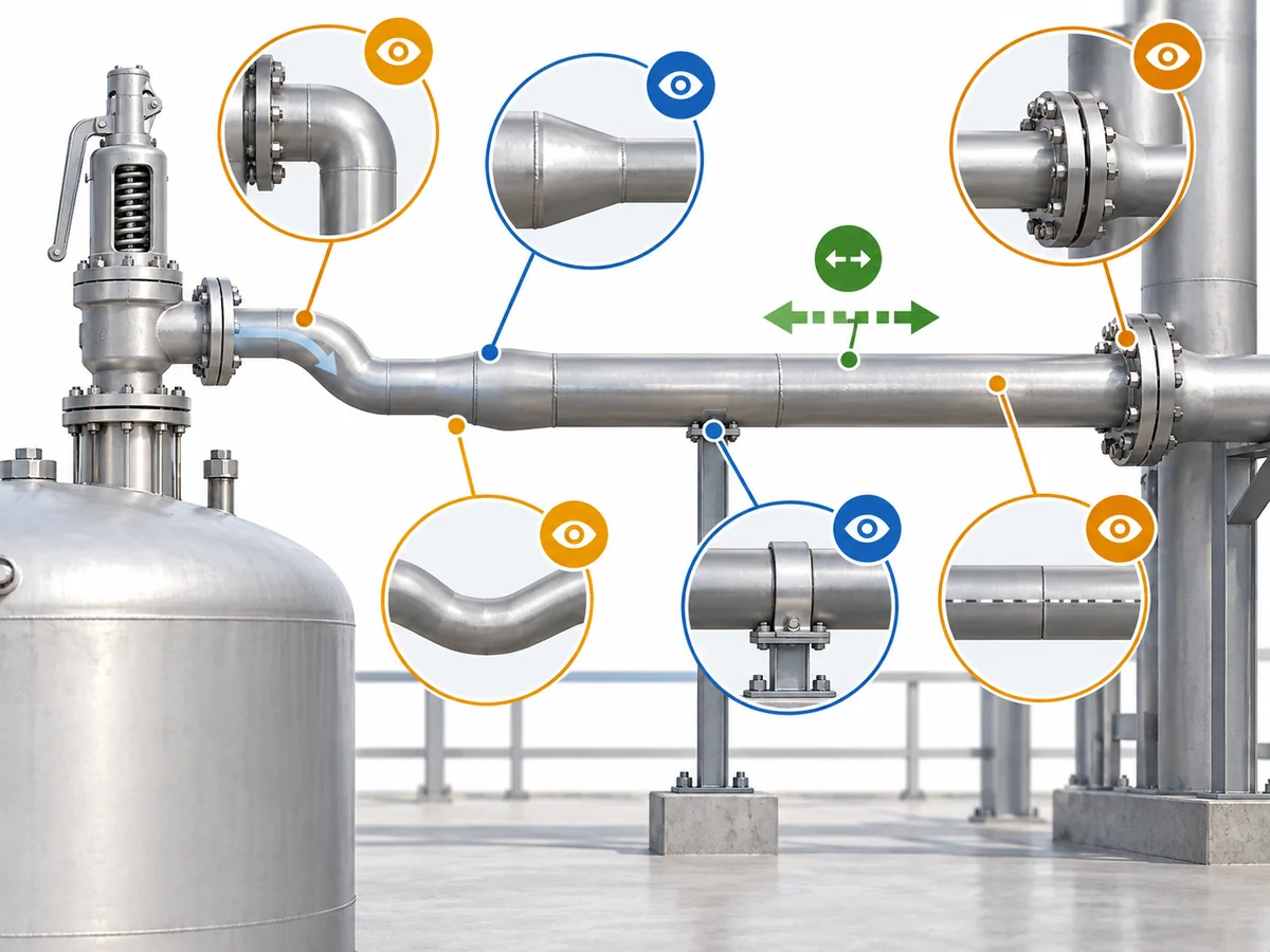
The discharge line should be reviewed as both a hydraulic path и mechanical installation.
Hydraulic path
Confirm the features that can materially affect downstream resistance and outlet pressure:
- outlet pipe size and actual flow area;
- developed length;
- elbows, reducers and other fittings;
- restrictions or downstream equipment;
- elevation changes where relevant;
- common-header connection;
- pressure in the receiving system;
- applicable header or simultaneous-relief basis.
The valve outlet flange size is an input, not proof that the connected line is hydraulically adequate.
Fluid and phase path
The relieving phase also matters. The engineering basis should identify whether the discharge is vapor, liquid, flashing or potentially two-phase under the governing case.
Where the installed system can collect liquid or condensate, applicable drainage requirements should be checked. OSHA, for example, contains condensate provisions for particular covered LP-Gas installations, but that does not justify turning them into a universal drain requirement for every LPG relief line. OSHA LP-Gas requirements
Mechanical path
Hydraulic acceptability does not answer every installation question. The outlet arrangement should also be reviewed for:
- discharge reaction loads;
- pipe support;
- alignment at the valve;
- thermal expansion;
- vibration or other piping loads transferred to the valve or protected equipment.
These mechanical checks are separate from the calculation of built-up back pressure.
Documentation path
Finally, the physical installation should match the data used for the valve review. Relevant project documents may include the approved discharge arrangement, P&ID or piping sketch, downstream-pressure calculation, manufacturer instructions and project-specific relief-system basis.
The practical check is:
Can the required relief flow reach its approved destination under the same conditions used to evaluate the safety valve?
If the answer depends on unknown piping, header or disposal-system information, the valve candidate is not ready for final acceptance.
What Discharge-System Data Should Go Into the RFQ, and When Should the Review Be Put on Hold?
A useful LPG safety-valve RFQ describes both the relief duty and the downstream system. A request containing only medium, connection size and pressure does not give the supplier enough information for a meaningful discharge/back-pressure review.
| Ввод данных для запроса коммерческого предложения | Почему это важно |
|---|---|
| Protected equipment / tag | Identifies the pressure-protection duty |
| Достоверный сценарий сброса давления | Defines the governing case |
| LPG composition or specified fluid | Establishes the service basis |
| Relieving phase/state | Identifies vapor, liquid, flashing or other relevant behavior |
| Требуемая пропускная способность | Defines the flow duty |
| Set and relieving conditions | Establish the pressure basis |
| Температура сброса | Supports valve/component review |
| Место назначения сброса | Defines atmosphere, flare, closed system or another route |
| Superimposed back-pressure range | Shows pressure that may exist before opening |
| Постоянное или переменное условие | Shows how downstream pressure can change |
| Накопленное противодавление | Shows outlet pressure produced by relief flow |
| Common-header / flare basis | Explains the downstream calculation context |
| Outlet-piping arrangement | Supports hydraulic and installation review |
| Candidate valve architecture | Identifies what is being screened |
| Material / seat / seal requirements | Поддерживает проверку совместимости |
| Governing standard / project edition | Defines the required documentation basis |
| Vendor sizing / capacity / limit evidence | Supports verification of the actual candidate |
The supplier’s valve documentation can establish what the candidate is designed and documented to do. It does not, by itself, approve the complete installed relief and disposal system.
Use HOLD when missing information can change the decision
Приведенные ниже термины представляют собой engineering-screening framework used on this page, not regulatory or code classifications.
ПЕРЕЙТИ К ИНЖЕНЕРНОЙ ПРОРАБОТКЕ / ЗАПРОСУ КП means the relief duty, discharge destination, downstream-pressure basis and candidate requirements are defined well enough for technical evaluation.
ОСТАНОВИТЬ means an unresolved input could materially change valve selection or the outlet-system review. Examples include an unknown discharge destination, unresolved relieving phase, missing required capacity, undefined superimposed or built-up back pressure, an undefined common-header case, missing model-specific limits or an unresolved governing project basis.
KNOWN MISMATCH should be used only where an actual project requirement and an actual documented candidate condition are already known to conflict. It should not substitute for missing data.