Technik von Sicherheitsventilen mit Balg und Druckausgleich Die Haubenentlüftung an einem Sicherheitsventil mit Balg und Druckausgleich ist Teil der Druckreferenzanordnung um Balg und Federraum. Das Verschließen, das Belassen einer Transportkappe oder das Anschließen an ein System, das einen unbeabsichtigten Druck aufbringt, kann den vom Ventildesign angenommenen Zustand verändern. Wenn …

Technik von Sicherheitsventilen mit Balg und Druckausgleich
Die Haubenentlüftung an einem Sicherheitsventil mit Balg und Druckausgleich ist Teil der Druckreferenzanordnung um Balg und Federraum. Das Verschließen, das Belassen einer Transportkappe oder das Anschließen an ein System, das einen unbeabsichtigten Druck aufbringt, kann den vom Ventildesign angenommenen Zustand verändern. Wenn später Prozessfluid an der Entlüftung austritt, wird eine mögliche Balgleckage zu einem wichtigen Inspektionspfad. Die korrekte Entlüftungsanordnung hängt vom genauen Ventildesign, Medium und Phase, den Folgen einer gefährlichen Freisetzung, der Abblasetemperatur, dem Gegendruck am Auslass und dem Druck am vorgesehenen Entlüftungsziel ab. Bevor die Entlüftung geändert wird, sind die Herstellerzeichnung und die tatsächlichen Projektbedingungen zu prüfen, anstatt den Anschluss als einfachen Ablass oder ungenutzte Bohrung zu behandeln.
Schnelle Antwort:
Halten Sie die Haubenentlüftung in der für das gewählte Sicherheitsventil mit Balg und Druckausgleich erforderlichen Konfiguration. Verschließen Sie sie nicht nur deshalb, weil normalerweise nichts aus dem Anschluss austritt. Wenn ein gefährlicher Betrieb eine geführte Entlüftung erfordert, sind sowohl die sichere Eindämmung als auch der Druck zu bewerten, den die Führung auf die Haube ausüben kann. Unerwartete Prozessleckage aus der Entlüftung ist ein Hinweis, der untersucht werden muss, beweist aber für sich genommen keinen bestimmten Balgfehler, keine Verschiebung des Ansprechdrucks oder kein Kapazitätsergebnis.
Halten Sie die Haubenentlüftung in der für das gewählte Sicherheitsventil mit Balg und Druckausgleich erforderlichen Konfiguration. Verschließen Sie sie nicht nur deshalb, weil normalerweise nichts aus dem Anschluss austritt. Wenn ein gefährlicher Betrieb eine geführte Entlüftung erfordert, sind sowohl die sichere Eindämmung als auch der Druck zu bewerten, den die Führung auf die Haube ausüben kann. Unerwartete Prozessleckage aus der Entlüftung ist ein Hinweis, der untersucht werden muss, beweist aber für sich genommen keinen bestimmten Balgfehler, keine Verschiebung des Ansprechdrucks oder kein Kapazitätsergebnis.
Seitenumbruch:
Dieser Artikel konzentriert sich speziell auf die Druckreferenz der Haube, Verstopfung, Entlüftungsführung und Anzeichen für Balgfehler. Für den breiteren Einfluss des Auslassdrucks auf die Ventilkonfiguration siehe
Gegendruck und Faltenbalg.
Dieser Artikel konzentriert sich speziell auf die Druckreferenz der Haube, Verstopfung, Entlüftungsführung und Anzeichen für Balgfehler. Für den breiteren Einfluss des Auslassdrucks auf die Ventilkonfiguration siehe
Gegendruck und Faltenbalg.
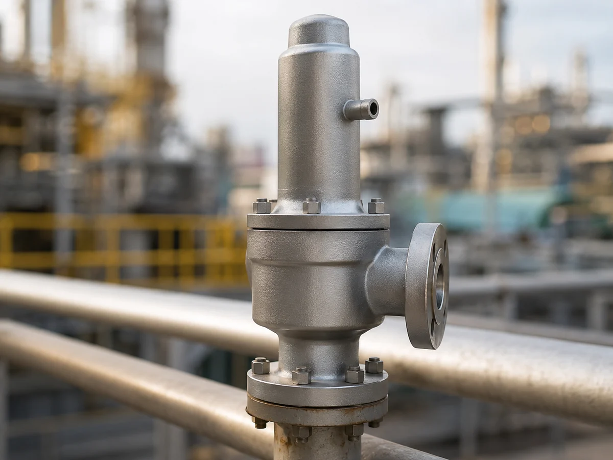
Final hochgeladenes WebP-Bild in Stufe 10C akzeptiert. Illustrative Industrieszene; kein Nachweis für ein bestimmtes ZOBAI-Modell, eine Zertifizierung oder ein installiertes Projekt.
Was bewirkt die Haubenentlüftung tatsächlich?
Ein Sicherheitsventil mit Balg und Druckausgleich verwendet eine Balganordnung, um den Einfluss des Gegendrucks am Auslass auf die Kräfte zu reduzieren, die das Öffnen des Ventils steuern. Der Balg ist wichtig, aber auch der Druckzustand auf der Haubenseite ist Teil des Designs.
Aus Sicht des Druckschutzes ist die relevante Frage nicht einfach, ob ein Entlüftungsloch vorhanden ist. Die Frage ist, auf welchen Druck der Haubenraum referenzieren soll.
Wenn die Konstruktion vorsieht, dass der Haubenbereich nahe am Atmosphärendruck oder einem anderen definierten Referenzzustand bleibt, kann eine blockierte Entlüftung oder eine extern druckbeaufschlagte Entlüftungsleitung diese Annahme beeinträchtigen.
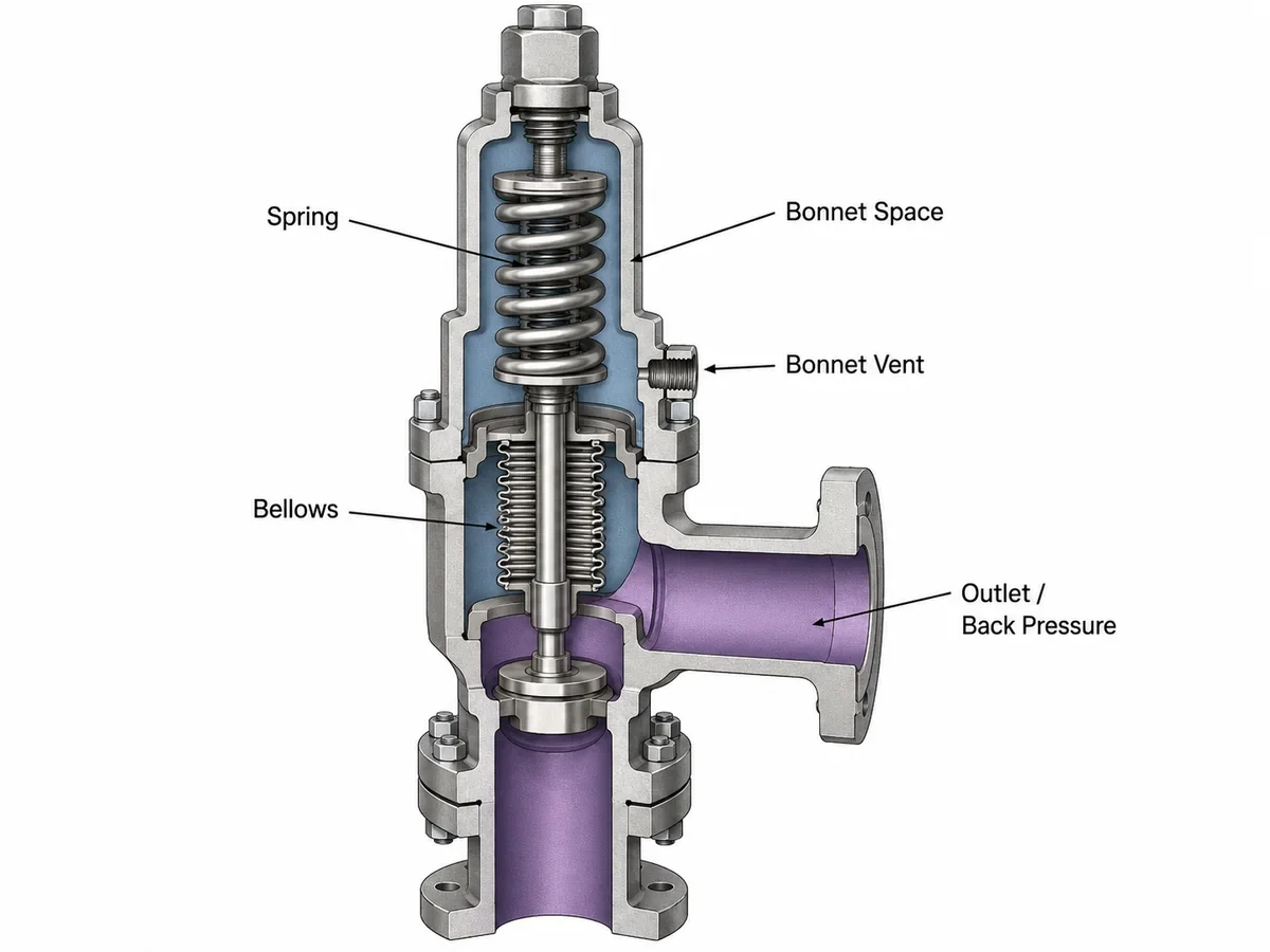
Endgültig hochgeladenes WebP-Bild, akzeptiert in Stufe 10C. Vereinfachte technische Darstellung; exakte Balggeometrie, wirksame Flächen und Entlüftungsanordnungen variieren je nach Ventilkonstruktion.
Haubendruck nicht mit Gegendruck am Auslass verwechseln
| Druckbegriff | Wo dies zutrifft | Warum dies hier relevant ist |
|---|---|---|
| Betriebsdruck | Geschützte Prozessausrüstung während des Normalbetriebs | Hilft, den normalen Betriebszustand zu definieren, definiert jedoch nicht den Haubenentlüftungsdruck. |
| Ansprechdruck | Druckbasis für das Öffnen des Ventils unter der geltenden Prüf-/Betriebsdefinition | Darf nicht aus dem Erscheinungsbild oder Zustand der Haubenentlüftung abgeleitet werden. |
| Überlagernder Gegendruck | Auslassdruck, der vor dem Öffnen des Ventils anliegt | Wirkt im Abgabesystem und muss von dem Druck unterschieden werden, der direkt auf die Haubenentlüftung ausgeübt wird. |
| Aufgebauter Gegendruck | Auslassdruck, der nach dem Öffnen durch den Abblasstrom entsteht | Hängt vom Widerstand des Abgabesystems ab und ist nicht identisch mit dem Haubenentlüftungsdruck. |
| Haubenentlüftungsdruck | Druck an der referenzseitigen Anschlussstelle der Haube | Kann die Druckumgebung um den Balg/Federraum beeinflussen, wenn die Konstruktion einen anderen Referenzzustand vorsieht. |
Technische Grenze:
Ein balanciertes Balgventil beseitigt nicht automatisch jede Gegendruckbegrenzung. Zulässiger überlagerter und aufgebauter Gegendruck, Druck-/Temperaturgrenzen des Balgs und zulässiger Haubendruck unterliegen der tatsächlichen Ventilkonstruktion und den Herstellerdaten.
Ein balanciertes Balgventil beseitigt nicht automatisch jede Gegendruckbegrenzung. Zulässiger überlagerter und aufgebauter Gegendruck, Druck-/Temperaturgrenzen des Balgs und zulässiger Haubendruck unterliegen der tatsächlichen Ventilkonstruktion und den Herstellerdaten.
Für den allgemeineren technischen Zusammenhang zwischen Auslassdruck und balancierter Konfiguration siehe
Faltenbalg-kompensierte Sicherheitsventile.
Was passiert, wenn die Haubenentlüftung verstopft oder blockiert ist?
Absichtliches Verschließen ist ein offensichtliches Risiko, aber Haubenentlüftungen können auch durch Schmutz, Farbe, Korrosionsprodukte, Insekten, Isolierung, Eis oder einen vorübergehenden Transportschutz, der nie entfernt wurde, verstopft oder eingeschränkt werden.
Absichtliches Verschließen
Eine Gewindeöffnung kann unfertig aussehen, sodass ein Wartungsteam versucht sein könnte, einen Blindstopfen oder eine Kappe zu installieren. Das sollte erst erfolgen, nachdem die Öffnung eindeutig identifiziert und die Anforderungen des Ventilherstellers geprüft wurden.
Umgebungsbedingte Verstopfung
Außeninstallationen erfordern möglicherweise besondere Aufmerksamkeit hinsichtlich Vereisung, Verschmutzung und Wetterschutz. Eine Schutzvorrichtung darf eine funktionale Entlüftung nicht versehentlich in eine versiegelte Haube verwandeln.
Die technische Versagenskette
| Schritt | Möglicher Zustand | Technische Konsequenz | Was verifiziert werden muss |
|---|---|---|---|
| 1 | Entlüftung wird verstopft oder eingeschränkt | Die freie Verbindung zur vorgesehenen Haubenreferenz könnte verloren gehen. | Tatsächlicher Belüftungszustand und vom Hersteller geforderte Anordnung |
| 2 | Der Haubendruck kann von der vorgesehenen Referenzbedingung abweichen | Die Druck-Kraft-Umgebung um den Balg und die bewegliche Baugruppe kann von der Konstruktionsannahme abweichen. | Tatsächlicher Haubendruck, Belüftungsbegrenzung und Ventilkonstruktion |
| 3 | Das Ventilverhalten kann sich ändern | Das Öffnungs-, Wiedereinsetz- oder Stabilitätsverhalten kann je nach Konstruktion beeinflusst werden. | Herstellerdaten und kontrollierte technische Bewertung |
| 4 | Der Bediener sieht nur eine blockierte Armatur | Das äußere Erscheinungsbild kann den Druckeffekt nicht quantifizieren. | Ohne Nachweis keine Rückschlüsse auf eine Sollwertverschiebung oder Kapazitätsänderung ziehen. |
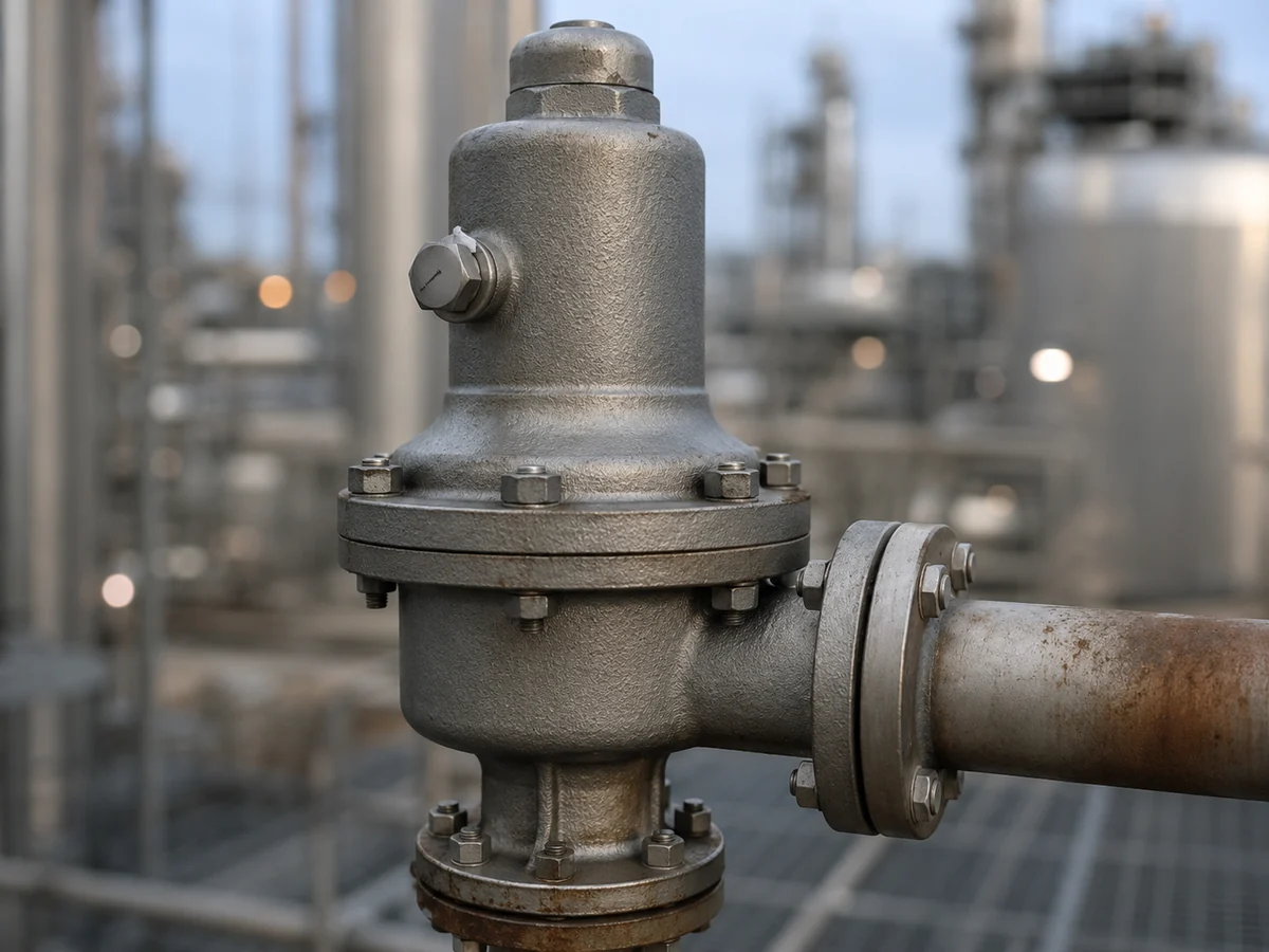
Endgültig hochgeladenes WebP-Bild in Stufe 10C akzeptiert. Nur realistische Darstellung; tatsächliche Entlüftungsführung und zulässige Einschränkungen müssen für die ausgewählte Ventilkonstruktion bestätigt werden.
Entlüftung zur Atmosphäre oder Ableitung an einen sicheren Ort?
Direkte atmosphärische Entlüftung und abgeleitete Entlüftung sollten als unterschiedliche technische Anordnungen behandelt werden und nicht als universelle Regeln.
Direkte Entlüftungsanordnung
Eine direkte Entlüftung kann geeignet sein, wenn die ausgewählte Ventilkonstruktion diese Referenz erfordert, das Medium kein unannehmbares Freisetzungsrisiko darstellt und die Umgebung die Öffnung nicht blockiert.
Abgeleitete Entlüftungsanordnung
Giftige, brennbare, korrosive oder anderweitig gefährliche Medien können eine kontrollierte Ableitung erfordern. Der Bestimmungsdruck, Einschränkungen, Entwässerung, Leitungslänge und Umwelteinflüsse müssen dann überprüft werden.
Vorläufige Entscheidungstabelle für die Entlüftungsführung
| Vorgeschlagene Anordnung | Potenzieller Nutzen | Hauptrisiko in der Technik | Erforderliche Prüfung |
|---|---|---|---|
| Direkte Entlüftung in die zugelassene lokale Atmosphäre | Einfache Druckreferenz mit minimalem Leitungsviderstand | Personengefährdung, Witterung, Kontamination oder Vereisung | Mittlere Gefährdung, Herstellervorgabe und Standort |
| Entlüftung zu einem sicheren offenen Ort geführt | Verlagert eine mögliche Freisetzung bei Balgversagen weg vom Personal | Verengung, Flüssigkeitsansammlung, Einfrieren oder Effekte langer Leitungen | Leitungsführung, Entwässerung, Endpunkt und Herstellerhinweise |
| Entlüftung an ein gemeinsames geschlossenes System angeschlossen | Potenzielle Rückhaltung gefährlicher Freisetzungen | Der Druck des aufnehmenden Systems kann auf den Haubenraum einwirken | Druckbereich des Zielsystems, Leitungsverluste, Ventilauslegung und Projektingenieurwesen |
| Entlüftung an einen druckvariablen Sammler angeschlossen | Zentrale Freisetzungsverwaltung | Variabler Haubendruck kann einen sich ändernden Kraftzustand erzeugen | Minimaler/maximaler Sammlerdruck und Herstellerfreigabe |
Keine neue Druckquelle schaffen:
Eine an ein geschlossenes oder unter Druck stehendes Ziel angeschlossene Entlüftung kann den Haubenraum einem Druck aussetzen, der von der Auslegungsreferenz abweicht. Sichere Rückhaltung und korrektes Druckverhalten des Ventils müssen gemeinsam geprüft werden.
Eine an ein geschlossenes oder unter Druck stehendes Ziel angeschlossene Entlüftung kann den Haubenraum einem Druck aussetzen, der von der Auslegungsreferenz abweicht. Sichere Rückhaltung und korrektes Druckverhalten des Ventils müssen gemeinsam geprüft werden.
Allgemeine Hinweise zu Abführung, Abstützung und Rohrleitungen finden Sie in der
Installationsanleitung für Sicherheitsventile.
Für weiterführende Informationen zu Entlastung, Entlüftung und Entsorgungssystemen siehe
API 521 Druckentlastungssysteme.
Was kann Leckage am Haubenentlüftungsventil über den Zustand des Balgs aussagen?
Unerwartetes Prozessgas, Dampf oder Flüssigkeit am Haubenentlüftungsventil kann auf einen Verlust der Druckgrenze hindeuten, die normalerweise den Haubenbereich von der Prozess- oder Auslassseite des Ventils trennt.
Balgleckage ist daher ein wichtiger Untersuchungspfad, aber Entlüftungsleckage sollte als Symptom und nicht als vollständige Diagnose behandelt werden.
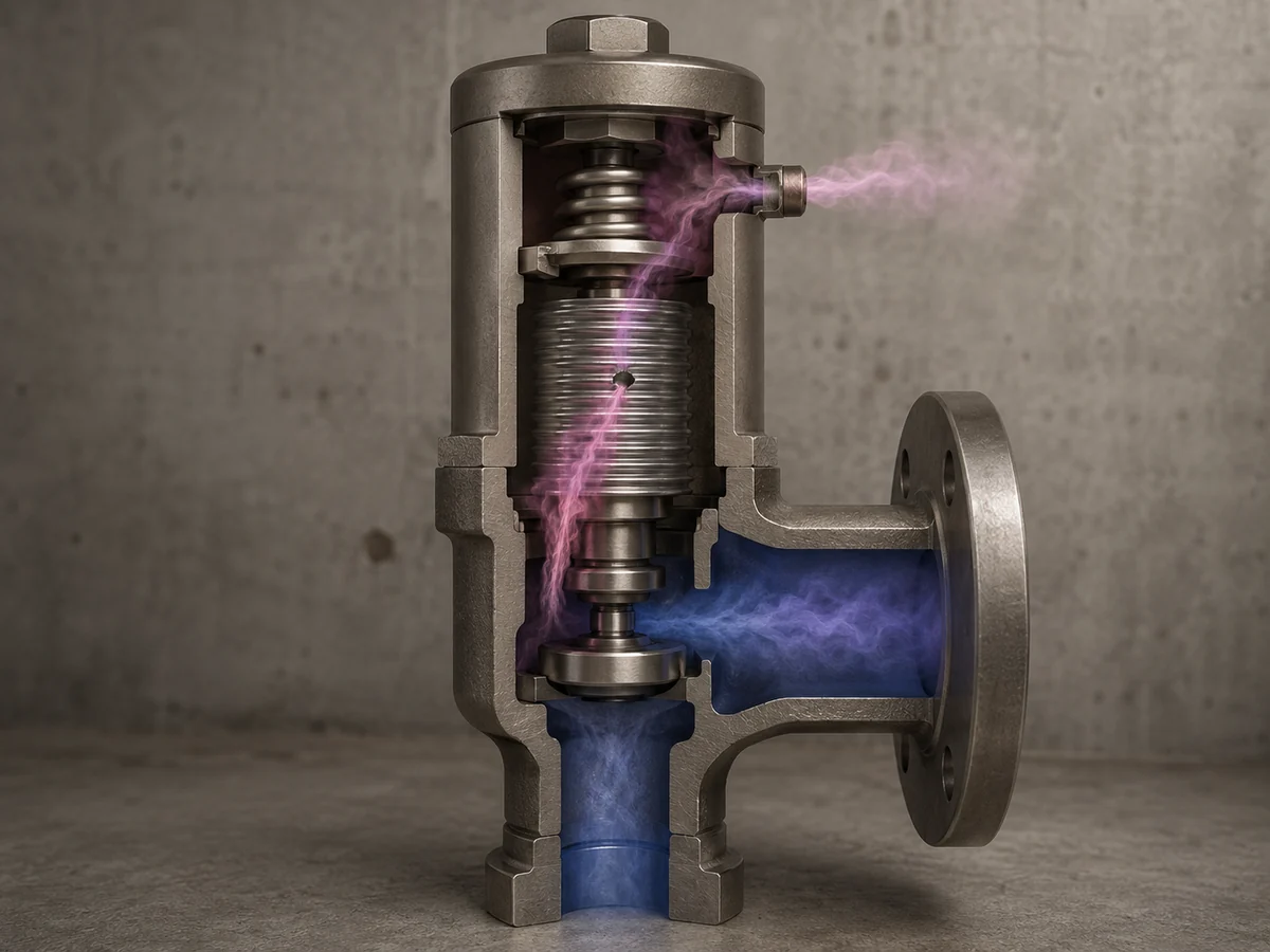
Endgültig hochgeladenes WebP-Bild in Stufe 10C akzeptiert. Nur konzeptionelle Darstellung; Entlüftungsleckage ist ein diagnostisches Symptom, kein Beweis für einen spezifischen Defekt, eine Sollwertänderung oder ein Kapazitätsergebnis.
Fehlerbehebungsmatrix für Leckage am Haubenentlüftungsventil
| Beobachtung | Mögliche Ursache | Als Nächstes prüfen | Noch keine Schlussfolgerung ziehen |
|---|---|---|---|
| Prozessdampf tritt an der Haubenentlüftung aus | Mögliche Balgleckage oder ein anderer interner Druckpfad | Ventilkonstruktion, Balgzstand, Betriebsdruck und Wartungshistorie | Dass der genaue Balgdefekt bekannt ist |
| Flüssigkeit tropft aus der verrohrten Entlüftung | Mögliche Prozessleckage, Kondensat oder externer Wassereintritt | Fluididentität, Entwässerung, Verrohrung und Balgintegrität | Dass die gesamte Flüssigkeit durch einen gerissenen Balg austrat |
| Entlüftung bleibt trocken | Keine offensichtliche externe Freisetzung | Normale Inspektion/Dokumentation nach Bedarf | Dass der Balg nachweislich intakt ist |
| Leckage beginnt nach Wartung | Mögliches Montage-, Balg- oder internes Dichtungsproblem | Reparaturunterlagen, Teileidentität, Montage und erforderliche Nachreparaturtests | Dass die Haubenentlüftung selbst den Defekt verursacht hat |
Eine ungeklärte Leckage nicht verschließen:
Das Abdichten der Entlüftung kann das Symptom verbergen, während sich der Druckzustand der Haube ändert. Der zugrunde liegende Ventilzustand und die erforderliche Druckschutzanordnung sollten überprüft werden.
Das Abdichten der Entlüftung kann das Symptom verbergen, während sich der Druckzustand der Haube ändert. Der zugrunde liegende Ventilzustand und die erforderliche Druckschutzanordnung sollten überprüft werden.
Führt ein Balgversagen immer zum gleichen Ventilverhalten?
Nein. Das Verhalten bei Balgversagen hängt von der Ventilkonstruktion ab.
Einige Anordnungen mit Balgkompensation verlassen sich in erster Linie auf den Balg zur Druckentkopplung. Andere Konstruktionen können zusätzliche Ausgleichsmerkmale enthalten, die das Ventilverhalten nach einem Balgdefekt beeinflussen sollen.
| Konstruktionsfrage | Warum es wichtig ist | Benötigte Nachweise |
|---|---|---|
| Erfolgt die Kompensation ausschließlich über den Balg? | Ein Verlust der Balgintegrität kann das vorgesehene Druck-Kraft-Verhältnis verändern. | Herstellerschnittzeichnung und Modelldaten |
| Ist ein zusätzliches Ausgleichsmerkmal vorhanden? | Das Ventil kann eine andere Ausfallreaktionsphilosophie aufweisen. | Bestätigte modellspezifische Konstruktionsdokumentation |
| Kann die Haubenentlüftung ein Balgleck sicher ableiten? | Das Störungsmanagement beeinflusst die Personengefährdung und die Anforderungen an die Leitungsführung. | Medium, Druck, Temperatur, Entlüftungsanordnung und Standortanforderungen |
| Ist ein Weiterbetrieb nach einem vermuteten Balgversagen akzeptabel? | Dies ist eine Entscheidung zum Druckschutz und zum Betrieb, nicht eine Schlussfolgerung aus einer Sichtprüfung. | Herstellerhinweise, Anlagenverfahren und verantwortliche technische Prüfung |
Zwei Fragen müssen daher getrennt bleiben:
- Ist der Balg noch intakt?
- Wie ist dieses konkrete Ventil konstruiert, um sich bei Verlust der Balgintegrität zu verhalten?
Keine der beiden Antworten lässt sich zuverlässig aus der allgemeinen Bezeichnung “balgkompensiertes Sicherheitsventil” ableiten.”
Häufige Fehler bei der Installation der Haubenentlüftung
| Entscheidung zur Installation | Hauptrisiko | Was zu bestätigen ist |
|---|---|---|
| Installieren eines Blindstopfens oder einer Schutzkappe | Verlust der vorgesehenen Druckreferenz am Bonnet | Herstellerzeichnung und Betriebsanforderung |
| Belassen des Transportschutzes | Unbeabsichtigte Blockierung | Montageanleitung und Endkontrolle |
| Anschluss an eine gemeinsame Druckleitung | Externer Druck auf das Bonnet | Zieldruck und Auslegungsgrenze des Ventils |
| Verwendung stark drosselnder Schlauchleitungen | Begrenzte Druckkommunikation oder Entlastungsweg bei Balgversagen | Hersteller und Projektierung |
| Bildung von Flüssigkeitssäcken | Entwässerungsprobleme, Einschränkung oder Einfrieren | Leitungsführung, Gefälle, Tiefpunkte und Umgebung |
| Abdecken der Entlüftung mit Isolierung oder Beschichtung | Verdeckter oder blockierter Entlüftungsweg | Isolierungsdetail und Wartungszugang |
| Abstützen der Entlüftungsleitung vom Ventil auf eine Weise, die Last hinzufügt | Mechanische Belastung einer kleinen Verbindung oder Haube | Unabhängige Unterstützung und Flexibilität der Rohrleitung |
| Änderung der Leitungsführung ohne Änderungsmanagement oder Dokumentaktualisierung | Zukünftige Inspektionen könnten auf einer veralteten Auslegungsbasis beruhen | Freigegebene Zeichnung, Änderungsprotokoll und Betriebsdokumentation |
Arbeiten an der Haubenentlüftung beheben auch nicht unabhängige Probleme wie Druckverlust am Einlass, unterdimensionierte Abblaseleistung oder übermäßigen Widerstand im Auslasssystem. Diese Bedingungen erfordern eine eigene technische Überprüfung.
Prüfliste für Haubenentlüftung
Sichtprüfung
- Identifizieren Sie die Haubenentlüftung eindeutig.
- Prüfen Sie auf unbefugte Stopfen oder Kappen.
- Bestätigen Sie, dass temporäre Schutzvorrichtungen entfernt wurden, wo erforderlich.
- Auf Schmutz, Farbe, Korrosion, Isolierung oder Eisblockaden prüfen.
- Verlegte Rohrleitungen und mechanische Abstützungen inspizieren.
- Den Endpunkt (Terminierung) identifizieren.
- Auf unerwartete Prozesslecks achten.
- Auf offensichtliche Flüssigkeitsfallen oder Entwässerungsprobleme prüfen.
Dokumentenprüfung
- Hersteller und genaues Modell
- Schnittzeichnung
- Balgkonfiguration
- Hilfsausgleichsvorrichtung, falls vorhanden
- Vorgesehene Anordnung der Haubenentlüftung
- Medium und Phase
- Betriebs- und Entlastungstemperaturen
- Betriebs- und Ansprechdrücke
- Gegendruckbedingungen
- Wartungs- und Balg-Inspektionshistorie
Inspektions-Hold-Punkte
- Den Entlüftungsanschluss erst ändern, wenn bestätigt ist, dass es sich um eine Haubenentlüftung handelt und der erforderliche Druckbezug verstanden wurde.
- Eine freie Entlüftung nicht als Nachweis dafür werten, dass der Balg intakt ist.
- Festgestellte Prozesslecks nicht als Wartungsabkürzung abdichten.
- Keinen neuen Entlüftungskopf einbauen, ohne den Druckbereich am Endpunkt zu bestätigen.
- Aus diesem Artikel kein universelles Inspektionsintervall ableiten; die Inspektionshäufigkeit hängt von der Schwere des Betriebs, den Herstellerangaben, den Anlagenverfahren und den geltenden Anforderungen ab.

Endgültig hochgeladenes WebP-Bild, akzeptiert in Stufe 10C. Illustrative Inspektionsszene; kein Nachweis für ein bestimmtes ZOBAI-Projekt, eine Zertifizierung oder ein Testergebnis.
Entscheidungsmatrix für Haubenentlüftung nach Betriebsbedingungen
| Betriebsbedingung | Hauptbedenken zur Entlüftung | Was zu bestätigen ist | Technische Ausrichtung |
|---|---|---|---|
| Sauberes, ungefährliches Gas oder Dampf | Aufrechterhaltung der vorgesehenen Druckreferenz | Herstellervorgabe zur Entlüftung und Umgebung | Direkte Anordnung kann möglich sein, wenn genehmigt |
| Giftiger oder entzündlicher Dampf | Freisetzung nach möglicher Balg-Leckage | Gefahreneinstufung und Abschluss | Geeignete sichere Entlüftungsführung prüfen |
| Korrosives Medium | Korrosive Freisetzung nach Balg-Schaden | Kompatibilität von Balg, Rohrleitungen und exponierten Materialien | Material- und Leitungsprüfung |
| Außenbereich mit Frostgefahr | Vereisung | Schutz vor Feuchtigkeit, Temperatur und Witterung | Verstopfung ohne Abdichten der Entlüftung verhindern |
| Schmutzige oder staubige Umgebung | Schutz vor Fremdstoffen | Schutzmethode und Inspektionszugang | Freien Druckausgleich aufrechterhalten |
| Entlüftung an ein anderes System angeschlossen | Unbeabsichtigter Haubendruck | Zieldruck, Einschränkung und Entwässerung | Prüfung durch Hersteller und Systemtechnik |
| Unerwartete Prozessleckage | Möglicher Verlust der Balg-Integrität | Ventilkonstruktion und tatsächliche Leckagequelle | Eskalation zur kontrollierten Inspektion |
Diese Matrix ist ein Screening-Werkzeug. Sie ersetzt keine herstellerspezifischen Entlüftungsdruckgrenzen, Balggrenzen oder Projektierung.
Was die Haubenentlüftung nicht beweist
| Beobachtung | Was sie Ihnen sagen kann | Was es nicht beweist |
|---|---|---|
| Entlüftung erscheint offen und frei | Keine sichtbare Blockade | Balgintegrität |
| Entlüftung ist verstopft | Druckreferenz kann beeinträchtigt sein | Exakter Einfluss auf das Öffnungsverhalten |
| Prozessflüssigkeit tritt an der Entlüftung aus | Möglicher interner Druckgrenzenfehler | Exakte Position des Balgfehlers |
| Keine sichtbare Leckage | Keine offensichtliche externe Freisetzung | Ansprechdruck, Sitzdichtheit oder erforderliche Kapazität |
| Entlüftung erreicht einen vorgesehenen sicheren Ort | Endpunkt ist definiert | Dass Entlüftungsdruck, Einschränkung oder Materialverträglichkeit akzeptabel sind |
Kapazitätsgrenze:
Der Zustand der Haubenentlüftung belegt nicht die erforderliche oder herstellerdokumentierte/zertifizierte Abblaseleistung. Der Ansprechdruck ist keine Kapazität, und die Größe der Ein-/Auslassanschlüsse belegt nicht die gewählte Düse oder die Schutzkapazität.
Für den separaten Zusammenhang zwischen erforderlicher Abblasemenge, gewählter Düse und dokumentierter Kapazität siehe
Sicherheitsventil-Auslegung und zertifizierter Abblaseleistung
Leitfaden.
Der Zustand der Haubenentlüftung belegt nicht die erforderliche oder herstellerdokumentierte/zertifizierte Abblaseleistung. Der Ansprechdruck ist keine Kapazität, und die Größe der Ein-/Auslassanschlüsse belegt nicht die gewählte Düse oder die Schutzkapazität.
Für den separaten Zusammenhang zwischen erforderlicher Abblasemenge, gewählter Düse und dokumentierter Kapazität siehe
Sicherheitsventil-Auslegung und zertifizierter Abblaseleistung
Leitfaden.
Welcher Test oder welches Dokument beantwortet welche Frage?
Die Inspektion der Haubenentlüftung ist nur ein Teil der Überprüfung des Ventilzustands. Unterschiedliche Tests und Aufzeichnungen beantworten unterschiedliche technische Fragen und sollten nicht als austauschbar behandelt werden.
| Nachweis | Beantwortete Hauptfrage | Was es nicht ersetzt |
|---|---|---|
| Sichtprüfung der Haubenentlüftung | Ist die Entlüftung sichtbar offen, verlegt und frei von offensichtlichen Schäden oder Leckagen? | Balgintegritätstest, Ansprechdruckprüfung oder Kapazitätsüberprüfung |
| Hersteller-Schnittzeichnung / Datenblatt | Wie ist die vorgesehene Ventilkonstruktion und die Anordnung der Haubenentlüftung? | Prüfung des tatsächlichen Zustands des installierten Ventils |
| Ansprechdruck-Verifizierung | Öffnet das Ventil unter dem anwendbaren Verfahren beim geforderten Prüfdruck? | Bestimmung der erforderlichen/zertifizierten Kapazität oder Bestätigung des Faltenbalgzustands |
| Dichtheitsprüfung des Sitzes | Erfüllt die Sitzleckage die anwendbare Abnahmekriterien? | Faltenbalg-Leckdiagnose oder Kapazitätsverifizierung |
| Faltenbalg-Inspektion / genehmigte Integritätsprüfung | Wie ist der Zustand des Faltenbalgs gemäß dem anwendbaren Wartungsverfahren? | Berechnung der Entlastungslast oder Überprüfung des Gegendrucks im System |
| Kapazitätsdokumentation | Welche dokumentierte/zertifizierte Entlastungsleistung gilt unter definierten Bedingungen? | Bestätigung, dass das installierte Entlastungsszenario und die Rohrleitungen korrekt sind |
| Wartungs-/Reparaturaufzeichnung | Welche Arbeiten, Teile und Prüfungen nach der Reparatur wurden durchgeführt? | Aktuelle Feldinspektion bei verändertem Zustand |
Die erforderliche Dokumentation und der Prüfumfang müssen gegen das ausgewählte Ventil, die Herstelleranweisungen, den anwendbaren Code, den Reparaturweg und die Projektspezifikation bestätigt werden.
Material- und Medienprüfungen für die Entlüftungsführung des Haubenraums
Die Entlüftungsführung ist nicht nur eine Frage des Drucks. Wenn die Integrität des Faltenbalgs verloren geht, können Teile des Entlüftungswegs der Haube, die normalerweise trocken sind, Prozessmedium ausgesetzt sein. Die Materialprüfung sollte daher sowohl den möglichen Fehlerzustand als auch den Normalbetrieb berücksichtigen.
| Betriebsfaktor | Zu prüfende Komponenten | Hauptanliegen |
|---|---|---|
| Korrosives Prozessmedium | Faltenbalg, haubenseitig exponierte Teile, Entlüftungsrohre, Fittings und Abschlussmaterialien | Ein defekter Faltenbalg kann normalerweise isolierte Komponenten korrosivem Medium aussetzen. |
| Hohe Entlastungstemperatur | Faltenbalg, Federraum, Haube, Entlüftungsrohr, Dichtungen/Dichtringe soweit zutreffend | Die Temperaturbeständigkeit muss den relevanten Störungs- und Leitungszustand abdecken. |
| Kondensierender Dampf | Entlüftungsleitung, Tiefpunkte, Entwässerungsanordnung und Endpunkt | Kondensat kann zu Verengung, Korrosion oder Einfriergefahr führen. |
| Giftiges oder entzündliches Medium | Entlüftungsrohrleitung, Verbindungen, Zielort und Überwachungsanordnung soweit zutreffend | Das Freisetzungsmanagement muss berücksichtigt werden, ohne einen unzulässigen Haubendruck aufzuerlegen. |
| Verschmutzter oder polymerisierender Dienst | Faltenbalgbereich, Entlüftungsöffnung und jede Kleinstleitungsführung | Ablagerungen können Bewegung oder Druckkommunikation einschränken. |
| Außenbereich mit niedrigen Temperaturen | Entlüftungsauslass, Tiefpunkte und Wetterschutz | Feuchtigkeit oder Kondensat kann gefrieren und den Weg blockieren. |
Materialgrenze:
Eine Werkstoffbezeichnung des Gehäuses allein beweist nicht die Eignung von Haubenentlüftung oder Faltenbalg. Bestätigen Sie den Faltenbalg, betroffene Innenteile, Federraum, Dichtungen/Dichtringe und jede Entlüftungsleitung gegenüber dem tatsächlichen Medium und den Temperaturen.
Eine Werkstoffbezeichnung des Gehäuses allein beweist nicht die Eignung von Haubenentlüftung oder Faltenbalg. Bestätigen Sie den Faltenbalg, betroffene Innenteile, Federraum, Dichtungen/Dichtringe und jede Entlüftungsleitung gegenüber dem tatsächlichen Medium und den Temperaturen.
Was vor Änderung der Haubenentlüftungsanordnung zu bestätigen ist
Ändern Sie die Entlüftung nicht nur auf Basis des Anschlussgewindes oder nahegelegener Rohrleitungen. Die Entlüftungsentscheidung sollte mit der geschützten Ausrüstung und der tatsächlichen Grundlage des Entlastungssystems verknüpft sein.
Geschützte Ausrüstung und Entlastungsbasis
- Geschütztes Equipment
- Maßgeblicher Entlastungsfall
- Betriebsdruck
- MAWP oder Auslegungsdruck
- Ansprechdruck
- Erforderliche Entlastungskapazität und Kapazitätsbasis
- Entlastungstemperatur
Betriebsbedingungen und Gegendruck
- Medium und Phase
- Toxische, entzündliche oder korrosive Eigenschaften
- Überlagernder Gegendruck
- Aufgebauter Gegendruck
- Konstanter oder variabler Druck
- Abblaseleitungsanordnung
Ventilkonstruktion
- Hersteller
- Exaktes Modell/Typ
- Balgenkonstruktion und -material
- Federumgebung
- Sitz-/Dichtungskonstruktion, sofern relevant
- Zusätzliche Ausgleichsfunktion, falls vorhanden
- Entlüftungsanschluss am Haubenoberteil
- Vom Hersteller freigegebene Haubenreferenz
Vorgeschlagene Entlüftungsführung
- Direkte oder verrohrte Anordnung
- Leitungsgröße und -länge
- Formstücke und Einschränkungen
- Entwässerung und Tiefpunkte
- Ableitungsort
- Mindest- und Maximaldruck des Aufnahmesystems
- Umwelteinflüsse
- Materialien der Entlüftungsleitung
Erforderliche Informationen für eine technische Prüfung oder RFQ
- Vorhandenes Ventiltypenschild und klare Fotos
- Aktuelles Datenblatt und Schnitt-/GA-Zeichnung, falls verfügbar
- Geschützte Ausrüstung und maßgebliches Entlastungsszenario
- Medium, Phase und Gefahreneigenschaften
- Betriebsdruck, MAWP/Konstruktionsdruck und Ansprechdruck
- Erforderliche Abblasekapazität und Berechnungsgrundlage, falls verfügbar
- Entlastungstemperatur
- Überlagerter und aufgebauter Gegendruck
- Anordnung der Einlass- und Auslassleitungen
- Aktuelle Haubenentlüftung und Ableitung
- Vorgeschlagene neue Entlüftungsführung und Druckbereich des Aufnahmesystems
- Balg, Innenteile und Materialien der Entlüftungsleitung, falls bekannt
- Anwendbarer Code, übernommene Ausgabe, Projektspezifikation und geforderte Dokumente
Wenn die Inspektion zu einem umfassenderen Ventilaustausch oder einer Konfigurationsprüfung führt, verwenden Sie die
Leitfaden zur Auswahl von Sicherheitsventilen
als nächsten Schritt, anstatt das Ventil nur nach Aussehen oder Anschlussgröße zu ersetzen.
Zusammengesetzte Ingenieurszenarien
Szenario 1 — Außenentlüftung durch Eis blockiert
Beobachtung: Ein Balg-Sicherheitsventil mit Gegendruckausgleich ist im Freien installiert, und Feuchtigkeit gefriert um die Haubenentlüftung.
Technische Überlegung: Die Haube kann möglicherweise die vom Ventildesign vorgesehene Druckreferenz nicht mehr aufrechterhalten.
Korrekturrichtung: Bestätigen Sie die genehmigte Entlüftungsanordnung, stellen Sie einen freien Entlüftungsweg gemäß der geltenden Anlagenvorschrift wieder her und untersuchen Sie die Quelle von Feuchtigkeit oder Kondensat.
Vorbeugung: Verwenden Sie eine vom Hersteller/Projekt genehmigte Wetterschutzanordnung, die eine Umgebungsblockade verhindert, ohne die Entlüftung abzudichten oder unbeabsichtigt unter Druck zu setzen.
Szenario 2 — Gefährlicher Dampf erfordert abgeführte Entlüftung
Beobachtung: Die geschützte Ausrüstung enthält einen gefährlichen Dampf, und eine direkte lokale Freisetzung nach einem möglichen Balg-Leck ist gemäß der Sicherheitsphilosophie des Standorts nicht akzeptabel.
Technische Überlegung: Die Führung der Entlüftung kann das Freisetzungsmanagement verbessern, aber ein geschlossenes oder druckvariables Ziel kann Druck auf die Haube ausüben.
Korrekturrichtung: Überprüfen Sie Zieldruck, Leitungsbeschränkung, Entwässerung, Materialverträglichkeit und Endpunkt zusammen mit den Anforderungen des Ventilherstellers.
Vorbeugung: Nehmen Sie die Haubenentlüftungsanordnung und den Zieldruckbereich in das Projektdatenblatt und die Rohrleitungsprüfung auf, anstatt die Entlüftung als Feldinstallationsdetail zu behandeln.
Szenario 3 — Prozessfluid tritt an der Haubenentlüftung aus
Beobachtung: An einer Haubenentlüftung, die zuvor keine Freisetzung zeigte, wird Prozessdampf festgestellt.
Technische Überlegung: Ein Verlust der Balgintegrität oder ein anderer interner Druckpfad wird zu einem plausiblen Versagensmechanismus.
Korrekturrichtung: Befolgen Sie den genehmigten Standortentscheidungsprozess für die Aufrechterhaltung des Überdruckschutzes, während Ventilkonstruktion, Balgzustand, Wartungshistorie und erforderliche Prüfungen überprüft werden.
Vorbeugung: Bewahren Sie Reparaturaufzeichnungen auf, verifizieren Sie Ersatzteile und Wartungsnachprüfungen, und verwenden Sie das Verschließen der Entlüftung nicht als Ersatz für die Diagnose.
Dies sind zusammengesetzte technische Szenarien für Schulungszwecke. Sie repräsentieren keine Kundenprojekte, ZOBAI-Feldtestaufzeichnungen oder modellspezifische Leistungsnachweise.
Technische Referenzen und technische Grenzen
Die Haubenentlüftung sollte als Teil der vollständigen Druckentlastungsvorrichtungsinstallation und des Entlastungs-/Entsorgungssystems überprüft werden. Die folgenden Referenzen erfüllen unterschiedliche Evidenzrollen; herstellerspezifische Beispiele begründen nicht die Konstruktion oder Leistung jedes balancierten Balg-Sicherheitsventils.
-
Spirax Sarco — Sicherheitsventilinstallation
— Installationsanleitung zur Haubenentlüftung bei balancierten Ventilen, Blockierung durch Fremdmaterial oder Eis und Drucküberlegungen. -
European Process Safety Centre — Lernblatt zu balancierten Balg-PSVs
— Prozesssicherheits-Schulungsmaterial, das sich mit einem Versandstopfen an einer Haubenentlüftung eines balancierten Balgventils und damit verbundenen Entlüftungsvorsichtsmaßnahmen befasst. -
LESER — Designgrundlagen
— technische Referenz des Herstellers zu Haubendruckzonen und Hilfskolbenkonfigurationen mit Druckausgleich. -
LESER — Engineering-Handbuch
— Herstellerhinweise zur sicheren Ableitung von brennbaren, giftigen oder korrosiven Medien. -
Emerson Crosby — Erkennung von Balglecks
— modellspezifisches Beispiel zur Überwachung von Balglecks, einem Backup-Kolben und Emissionen über die Haubenentlüftung; es stellt keine allgemeingültige Regel für die Ventilkonstruktion dar. -
American Petroleum Institute – API 520 Teil II
— allgemeinerer Kontext zur Installation von Druckentlastungseinrichtungen. -
American Petroleum Institute – API-Norm 521
— allgemeinerer Kontext für Druckentlastungs- und Druckminderungssysteme.
Für das jeweilige Projekt sind die angewandte Normausgabe, die Herstelleranforderungen und die örtlichen Vorschriften zu prüfen. Diese Referenzen belegen keine Zertifizierung, Kapazität, Kennzeichnung oder modellspezifische Eignung eines bestimmten ZOBAI-Ventils.
Häufig gestellte Fragen
Warum benötigt ein balanciertes Balgsicherheitsventil eine Haubenentlüftung?
Die Haubenentlüftung trägt dazu bei, die erforderliche Druckreferenz auf der Haubenseite der balancierten Balg-Anordnung aufrechtzuerhalten. Der exakt erforderliche Druck und die Entlüftungskonfiguration hängen von der Ventilkonstruktion und den Herstellerdaten ab.
Kann die Haubenentlüftung eines balancierten Balgsicherheitsventils verschlossen werden?
Schließen Sie es nur dann an, wenn der ausgewählte Hersteller diese Anordnung ausdrücklich zulässt. Eine blockierte Entlüftung kann den im Ventildesign angenommenen Druckzustand der Haube verändern.
Kann ich die Motorhaubenentlüftung an ein geschlossenes Rohrleitungssystem anschließen?
Nur nach technischer Prüfung. Ein geschlossenes System kann für das Abblasemanagement in bestimmten Anwendungen geeignet sein, aber sein Mindest- und Höchstdruck, seine Begrenzungen, seine Entwässerung und sein Abschluss müssen mit der erforderlichen Druckreferenz des Haubenraums des Ventils kompatibel bleiben.
Was bedeutet ein Austritt von Flüssigkeit aus der Motorhaubenentlüftung?
Unerwartete Leckage von Prozessflüssigkeit kann auf einen Verlust der Balgintegrität oder einen anderen internen Leckagepfad hinweisen, abhängig von der Ventilkonstruktion. Sie sollte eine Untersuchung auslösen, anstatt sofort die Entlüftung zu verstopfen.
Bedeutet ein Leck an der Motorhaubenentlüftung immer, dass der Balg gerissen ist?
Nein. Es ist ein wichtiges Symptom, aber der tatsächliche Leckagepfad, der Zustand des Balgs und die Ventilkonstruktion müssen dennoch überprüft werden.
Sollten Haubenentlüftungen für giftige oder entzündliche Medien an einen sicheren Ort geführt werden?
Eine sichere Ableitung kann erforderlich sein, wenn eine mögliche Freisetzung eine unannehmbare Gefahr darstellt. Der genaue Bestimmungsort und die Rohrleitungsanordnung hängen vom Medium, den Standortanforderungen, der Ventilkonstruktion, dem Bestimmungsdruck und den Herstelleranweisungen ab.
Welche Informationen sollten vor der Änderung der Motorhauben-Entlüftungsleitung überprüft werden?
Bestätigen Sie das Ventilmodell und die Balgkonstruktion, geschützte Ausrüstung und Entlastungsszenario, Medium und Phase, Betriebsdruck, MAWP oder Auslegungsdruck, Ansprechdruck, Entlastungstemperatur, überlagerter und aufgebauter Gegendruck, vorgesehener Ziel-/Enddruck, Einschränkungen der Entlüftungsleitung und Materialien sowie die geltenden Hersteller- und Projektanforderungen.
Benötigen Sie eine technische Prüfung einer Haubenentlüftungsanordnung?
Senden Sie die geschützte Ausrüstung, das maßgebliche Entlastungsszenario, Medium und Phase, Betriebsdruck, MAWP oder Auslegungsdruck, Einstelldruck, erforderliche Entlastungskapazität und gegebenenfalls die Berechnungsgrundlage, Entlastungstemperatur, überlagerten und aufgebauten Gegendruck, Ventilhersteller/-modell, Balg- und Materialinformationen, Haubenentlüftungsanschluss, aktuelle Verrohrung, vorgeschlagenen Abschlussdruckbereich sowie verfügbare Zeichnungen oder Fotos.