腐蚀性介质安全阀指南 什么是耐腐蚀安全阀?材料、限值与选型核查 耐腐蚀安全阀是一种泄压装置,其承压边界、接液内件及外露功能部件均针对特定腐蚀性介质或环境进行选材。它并不只是不锈钢阀门。介质组成、浓度、相态、杂质、……

What Is a Corrosion-Resistant Safety Valve? Materials, Limits and Selection Checks
A corrosion-resistant safety valve is a pressure-relieving device whose pressure boundary, wetted internals and exposed functional parts are selected for a defined corrosive medium or environment. It is not simply a stainless-steel valve. The medium composition, concentration, phase, contaminants, normal and relieving temperature, pressure, condensate risk, external atmosphere and discharge system determine which materials and construction details require review. Corrosion resistance must cover the parts that control opening, flow, guidance and reseating—not only the body. The valve must still have the correct set pressure, documented relieving capacity, pressure-temperature rating, back-pressure response and installation. A material label, flange size or coating cannot prove application suitability; final selection requires model-specific manufacturer data, the adopted project standard and a complete service datasheet.
页面范围: This definition page explains what “corrosion-resistant safety valve” means and which engineering checks make that description credible. It does not provide a universal chemical-compatibility chart, perform relief sizing, promise a material grade, or replace a model-specific datasheet and project approval.
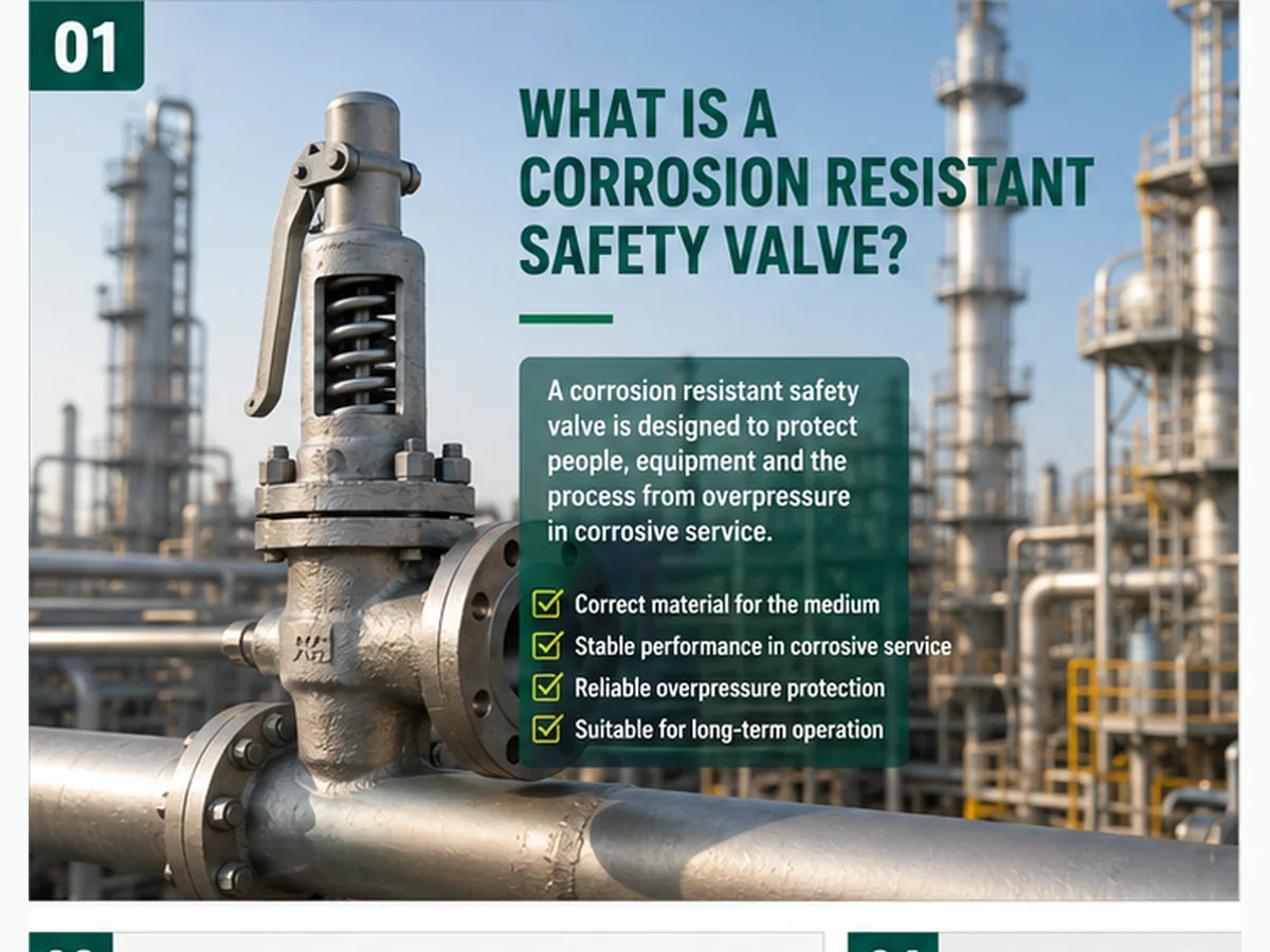
Industrial concept image; final material suitability and product details must be confirmed against the selected valve datasheet and project specification.
快速解答
A corrosion-resistant safety valve is selected for a specific corrosive fluid or environment, with material compatibility checked across the pressure boundary, trim, guiding parts, spring chamber, bellows, seals, bolting and discharge path. Stainless steel alone is not proof of compatibility. The valve must also satisfy the required set pressure, relieving capacity, temperature, back pressure, installation and documentation basis.
- Define the exact medium, concentration, phase, contaminants and relieving temperature.
- Review every wetted or exposed functional component, not only the body.
- Separate material suitability from required and certified/rated relieving capacity.
- Verify outlet back pressure, drainage, spring-chamber exposure and piping loads.
- Use the selected model datasheet and adopted project edition for final approval.
什么是耐腐蚀安全阀?
Corrosive media
材料审查
Capacity still required
RFQ data needed
Engineering definition
A corrosion-resistant safety valve is a safety valve whose materials and construction are selected so corrosion, environmental cracking, deposits or chemical attack do not prevent the device from opening, lifting, discharging, guiding, reseating and remaining pressure-tight for the specified service. Depending on the exposure, the design may use stainless steel or nickel alloy pressure parts, corrosion-resistant trim, compatible metal or soft seats, protected spring-chamber construction, a bellows, suitable gaskets and external corrosion protection.
It remains an overpressure-protection device. The selected valve must open according to its specified opening characteristic, pass the required relieving load on the stated fluid basis and reseat within the applicable design and project requirements. Product-family names do not replace the selected model datasheet. For the broader decision sequence, use the 安全阀选型指南.
Terminology boundary: safety valve, relief valve, PSV, PRV and SRV
Terminology varies by code family and industry. “Pressure relief valve” can be used as a broad device category, while “safety valve,” “relief valve” and “safety relief valve” may describe different opening characteristics or fluid applications. PSV and SRV are common project abbreviations. PRV is ambiguous because it can also mean pressure-reducing valve. The name alone cannot establish fluid basis, pop or proportional action, certified capacity, code marking or suitability; those points must come from the valve datasheet and applicable standard.
保护对象
These valves may protect reactors, pressure vessels, heat exchangers, separators, wet-gas systems, chemical storage or transfer equipment, scrubbers, pipelines and packaged systems. Selection starts with the protected pressure boundary and governing relief scenario, because those determine the required capacity, fluid phase, relieving temperature and discharge condition.
What “corrosion resistant” does not automatically mean
“Corrosion resistant” does not mean suitable for every acid, alkali, chloride-bearing liquid, solvent, sour gas, wet vapor, seawater atmosphere or mixed-phase process. It does not mean the body material protects the nozzle, disc, guide, spindle, spring, bellows, gasket, O-ring, bolting or outlet system. It also does not prove pressure rating, seat tightness, relieving capacity, code certification or inspection scope.
选型边界: Material compatibility is one independent qualification. Capacity, set pressure, operating margin, pressure-temperature rating, back pressure, installation and documentation must be verified separately. A valve may resist the medium and still be undersized, unstable or unacceptable for the project.
| 项目 | 实际意义 |
|---|---|
| 主要功能 | Automatic overpressure protection for a defined corrosive or corrosion-risk service. |
| 正常状态 | Closed and seat-tight to the specified acceptance basis during normal operation. |
| Opening basis | The specified set-pressure and opening characteristic under the applicable test and service conditions. |
| Corrosion review basis | Actual composition, concentration, phase, contaminants, normal and relieving temperature, pressure, condensate and external exposure. |
| 主要选型风险 | Treating a generic material name as proof of component compatibility, capacity, stability and documentation. |
Why Corrosive Service Changes Safety Valve Selection
Corrosion can disable the pressure boundary or the operating mechanism
Corrosion can thin or crack the body and bonnet, pit the nozzle and disc, increase guide or spindle friction, weaken the spring, perforate a bellows, attack a gasket or O-ring, obscure the nameplate and damage the inlet or outlet piping. A safety valve is a dynamic device: localized attack on a guiding or sealing surface can be more important than uniform wall loss elsewhere.
Composition, wetting phase, contaminants and relieving temperature control material behavior
Compatibility must be evaluated at the conditions the component actually sees. Dry gas can become wet during cooling; vapor can condense in a bonnet or discharge line; chlorides can concentrate in deposits; cleaning chemicals can create a different exposure from the process fluid. Normal and relieving temperature can change corrosion rate, soft-seat limits, gasket behavior and allowable pressure rating. Confirm the selected valve against the applicable 压力-温度额定值.
Corrosion products can cause leakage, sticking, unstable lift and poor reseating
The pressure boundary can remain apparently intact while deposits, crystallization, polymerization or corrosion products interfere with disc movement and seat contact. The resulting symptom may be leakage, delayed opening, restricted lift, flutter, chatter or failure to reseat. The symptom does not identify the root cause by itself; material evidence, operating history, piping data and inspection findings must be reviewed together.
复合工程工况: 干气数据表规定采用不锈钢阀体结构,但操作管线会周期性降温至酸性气体露点以下。冷凝液到达导向部位和出口腔室,产生沉积物和局部腐蚀。观察到的故障是停车后阀瓣卡涩。纠正措施是明确润湿工况,审查所有暴露部件和排放措施,并根据实际冷凝液化学组成选择材料。预防控制措施是在询价单(RFQ)中纳入露点和开停车工况。这是培训场景,不是客户记录。
用于含H2对于含硫油气生产或天然气脱硫工况,ISO 15156 / NACE MR0175 可能适用于抗开裂金属材料的选择。它是对适用设计规范的补充,而非替代。不应将其加入所有化工工况的询价单,也不应将其视为通用的酸、氯化物或下游炼油兼容性标准。
仅在 ISO 15156 / NACE MR0175 适用范围内的工况中使用该标准
| 工况系数 | 为何会改变选型 | 需确认事项 |
|---|---|---|
| 酸性或碱性介质 | 可能腐蚀承压件、内件、密封座和垫片;腐蚀行为随浓度和温度变化。 | 组成、浓度范围、污染物、相态、正常工作温度和泄放温度。 |
| 氯化物或海洋环境暴露 | 在敏感材料和工况下可能促进局部腐蚀或环境开裂。 | 氯化物来源、干湿暴露、温度、沉积物、缝隙、冲洗和外部大气环境。 |
| 湿气或腐蚀性蒸气 | 冷凝液可能使正常稳定运行期间未接触介质的部件暴露于腐蚀环境。 | 露点、启停工况、冷凝液化学性质、排放与出口管路布置。 |
| 含污物、易结晶或易聚合的介质 | 沉积物可能堵塞流道、增大摩擦力或损坏密封面。 | 固体颗粒、黏度、结晶/聚合倾向、清洗方式及维护记录。 |
| 泄放温度过高或过低 | 可能改变腐蚀机理、力学性能、弹簧特性及密封极限。 | 正常、异常及泄放温度,以及压力-温度额定值依据。 |
工程规则: 没有一种合金能够耐受所有腐蚀环境。选材应依据实际接触工况、可获得的试验或使用数据、力学性能要求、可维护性以及与相邻部件的相容性,而不是仅凭笼统的“耐腐蚀”标签。
耐腐蚀安全阀用于哪些场合?
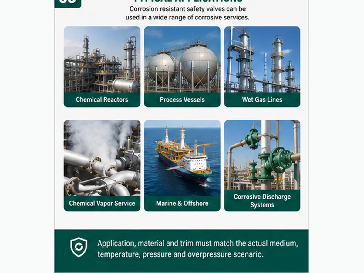
Simplified application map for RFQ orientation; actual valve location and material selection depend on the protected equipment, relief scenario and project review.
Chemical and process equipment
Reactors, pressure vessels, exchangers, separators and transfer systems may expose the inlet and wetted trim to acids, alkalis, solvents, catalysts or reaction products. The governing relief scenario and relieving composition may differ from normal operation.
Wet gas, vapor and condensing service
Wet gas and corrosive vapor require dew-point, condensate and drainage review because the valve and discharge system can see a liquid phase that is absent from the normal process description.
Outdoor, marine and corrosive atmospheric exposure
External attack can affect the bonnet, spring housing, bolting, cap, lever, vents, drains and nameplate even when the process fluid is noncorrosive. Coating, material, drainage and inspection access are separate decisions.
Hygienic service is a different selection problem
Hygienic duty centers on cleanability, drainability, surface finish and CIP/SIP or product-contact requirements. A hygienic valve may also face corrosion, but “sanitary” and “corrosion resistant” are not interchangeable product definitions.
Which Parts Need Corrosion Review?
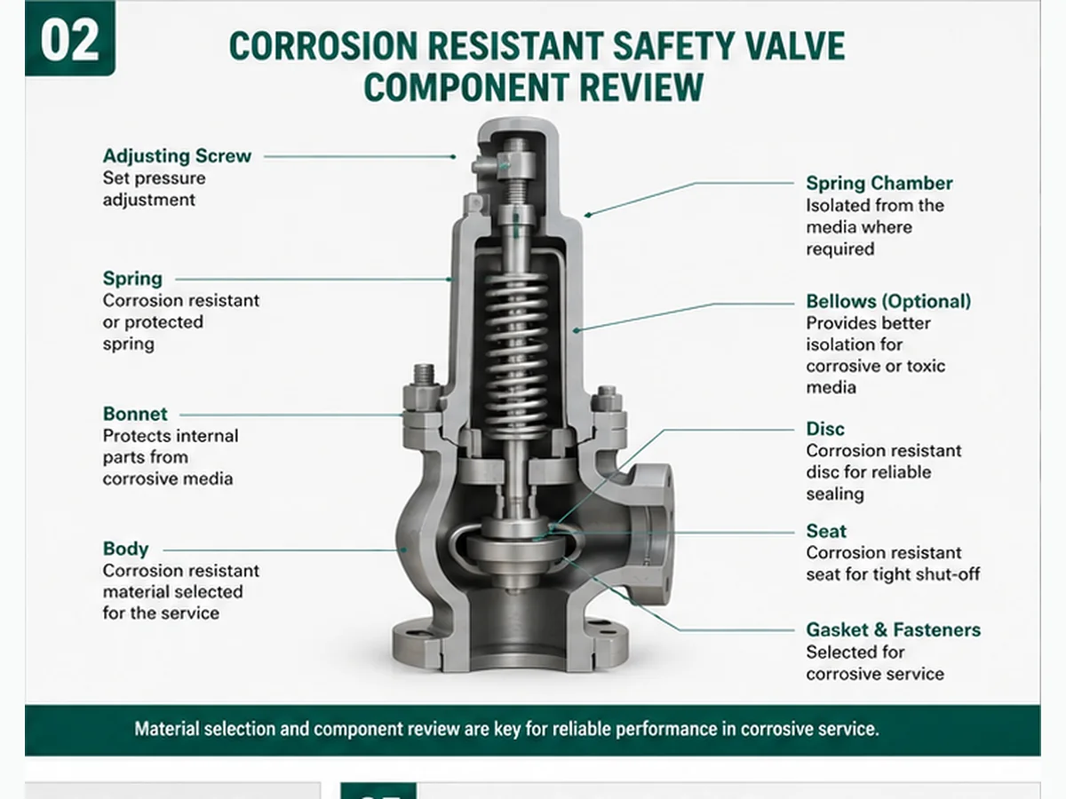
Simplified engineering illustration; not a model-specific cross-section, material guarantee or certified construction drawing.
Specifying only the body material is a frequent procurement error. The review should follow the pressure boundary, wetted flow path, moving and guiding mechanism, spring chamber, seals, fasteners and discharge-side exposure. Each component can have a different exposure and failure consequence.
| 部件 | Corrosion concern | What to confirm before RFQ |
|---|---|---|
| 阀体与阀盖 | General or localized corrosion, external attack, pressure-boundary thinning or cracking. | Material, casting/forging specification if required, pressure-temperature rating, corrosion allowance policy, inspection scope. |
| 阀座与阀瓣 | Pitting, erosion-corrosion, galling or deposits that change seat contact and lift. | Wetted materials, hardness pairing, medium cleanliness, velocity/phase change and maintenance method. |
| Seat / soft seat / O-ring | Chemical attack, swelling, hardening, permeation, extrusion or temperature damage. | Metal or soft-seat design, polymer grade, temperature limits, leakage acceptance and decompression behavior where relevant. |
| 导向套与阀杆 | Localized corrosion, deposits, galling or misalignment that increases friction. | Material pairing, clearances, condensate/solids exposure, cleaning and inspection evidence. |
| Spring and spring chamber | Corrosion or deposits that change spring force, movement or repeatability. | Bonnet environment, vent routing, bellows/protection need, spring material and coating limits. |
| 波纹管 | Corrosion, fatigue, perforation or blocked venting; failure can change back-pressure response. | Bellows alloy, movement, temperature, cyclic duty, internal/external exposure and vent route. |
| Gaskets, packing and seals | Chemical incompatibility, creep, relaxation, swelling or leakage. | Exact material, temperature/pressure limits, assembly procedure and replacement traceability. |
| Fasteners, cap and external parts | Atmospheric corrosion, seized adjustment parts, lost identification or poor access. | External environment, bolting material, coating system, nameplate protection and inspection access. |
If corrosive medium or outlet pressure can reach the spring chamber, 波纹管平衡式安全阀 or another protected construction may need review. A bellows is not a universal corrosion barrier: alloy, temperature, fatigue, venting, movement and failure mode remain model-specific.
复合工程工况: A replacement upgrades the body from carbon steel to stainless steel, but retains an incompatible nozzle, disc and guide material. The valve passes a shop set-pressure check, then develops seat leakage and rough movement in service. The engineering cause is component-level material mismatch, not an incorrect body grade. The correction is to review the full wetted and functional material schedule; the prevention control is a datasheet that names body, nozzle, disc, guide, spindle, spring, bellows, gasket and seat materials separately. This is an illustrative training case.
Main Design Options for Corrosive Media Safety Valve Review
Stainless steel and alloy construction
Material selection must match the corrosion mechanism and mechanical duty. “Stainless” is a family name, not a compatibility decision, and higher alloy content does not remove the need to review fabrication, hardness, galling and adjacent materials.
Balanced bellows or protected spring chamber
A bellows or protected bonnet may isolate selected parts from outlet pressure or corrosive discharge, but the bellows itself becomes a pressure- and fatigue-sensitive component. Its vent route and failure indication must remain open and correctly routed.
Metal seat, soft seat and gasket selection
Metal seats avoid polymer compatibility limits but can be sensitive to pitting and particles. Soft seats may reduce leakage when chemically and thermally suitable, but swelling, hardening, decompression and replacement traceability require review.
Lining and coating limitations
A coating or lining can support external or selected internal corrosion control only when the manufacturer approves its location, preparation, thickness, repair method and temperature/pressure service. It must not obstruct flow, clearances, vents or sealing surfaces.
Conventional spring-loaded and pilot-operated boundaries
Conventional valves are simple but can be sensitive to back pressure and bonnet exposure. Pilot-operated designs may offer different operating-margin and back-pressure behavior, yet sensing lines, pilots and seals can be vulnerable to plugging, condensate, crystallization or chemical attack.
Inspection, repair and document controls
Material records, set-pressure and seat-tightness results, as-found/as-left data, replacement-part traceability, resealing and management of change should be specified where required. These records do not replace capacity or installed-system review.
| Design option | When it may be reviewed | 边界条件 |
|---|---|---|
| Stainless-steel or alloy pressure parts | When corrosion data support the grade for the actual fluid, temperature and fabrication condition. | Not universal; grade, product form, heat treatment, hardness, welding and service exposure may matter. |
| Corrosion-resistant trim | When nozzle, disc, guide or spindle face localized attack, galling, erosion or deposits. | Trim must still move, guide, seal and retain the selected flow geometry. |
| Balanced bellows / protected chamber | When outlet pressure or corrosive discharge could affect spring-chamber components. | Bellows material, cyclic life, venting, temperature, movement and back-pressure limits require model data. |
| 软密封 | When lower leakage is needed and the elastomer or polymer is compatible with chemistry, pressure and temperature. | Chemical compatibility, decompression, aging and spare-part traceability must be confirmed. |
| Lining or coating | When approved for a defined surface and exposure as part of the manufacturer/project design. | Does not replace pressure-boundary, trim, seat, flow-area, inspection or code review. |
| Pilot-operated configuration | When the project needs its operating-margin or back-pressure characteristics and the medium is suitable for the pilot and sensing path. | Dirty, viscous, crystallizing, condensing or freezing service can affect pilot passages and seals; use model-specific limits. |
复合工程工况: A pilot-operated valve is selected to improve operating margin, but the process vapor condenses in the sensing line and leaves crystalline deposits. Opening becomes delayed and repeatability degrades. The correction is to review fluid cleanliness, phase behavior, sensing-line routing and an alternative valve architecture. The prevention control is to include condensate, solids and cleaning conditions in the valve-type decision. This is an illustrative scenario, not a product claim.
Preliminary Corrosive-Service Review Matrix
This matrix is a screening tool, not a material chart or final model selector. It identifies the information needed to define corrosion exposure and to keep material selection separate from overpressure-protection sizing.
| 问题 | 为何会改变决策 | What to send before RFQ |
|---|---|---|
| What equipment and pressure boundary are protected? | The equipment code, MAWP/design pressure and relief scenario establish the overpressure-protection basis. | Equipment type/tag, design documents, operating pressure, MAWP/design pressure and connection data. |
| 起控制作用的泄放工况是什么? | Blocked outlet, regulator failure, thermal expansion, reaction upset, tube rupture or fire exposure can change flow, phase and composition. | Scenario description, required capacity and calculation basis from the responsible engineer. |
| What is the exact medium at normal and relieving conditions? | Corrosion depends on composition, concentration, contaminants, wetting phase, temperature and pressure—not the trade name alone. | Composition range, contaminants, pH where meaningful, vapor/liquid/two-phase condition and relieving temperature. |
| Can condensation, solids, crystallization or polymerization occur? | Deposits and phase change can affect material exposure, clearances, seat contact, drainage and maintenance. | Dew point, solids, viscosity, crystallization/polymerization limits, startup/shutdown and cleaning plan. |
| Where does the valve discharge? | Atmospheric discharge, vent stacks and common headers change back pressure, corrosive exposure, drainage and reaction loads. | Outlet drawing, destination, header pressure, built-up back pressure, drains and support. |
| What evidence and inspection scope are required? | Material records, PMI, test records, capacity evidence and witness points affect acceptance and lead time. | Project specification, QA plan, document list, hold/witness points and traceability level. |
| What corrosion mechanism is credible? | Uniform attack, pitting, crevice corrosion, galvanic corrosion, erosion-corrosion and environment-assisted cracking require different controls. | Prior inspection findings, corrosion study, laboratory/service data, adjacent materials and fabrication condition. |
| Which pressure terms are confirmed? | Operating pressure, MAWP, set pressure, CDTP, overpressure, accumulation and relieving pressure affect different checks and should not be merged. | Project datasheet values with units, fluid/test basis, back pressure and adopted code edition. |
RFQ rule: “Corrosion-resistant safety valve” or “stainless-steel safety valve” is not a complete specification. At minimum, provide the real medium and concentration range, phase, contaminants, operating and relieving temperature, pressure terms, relief load, back pressure, component materials and evidence required.
Corrosion Resistance Does Not Prove Relieving Capacity
Corrosion resistance and relieving performance are independent engineering checks. A compatible material does not establish the required flow area, discharge coefficient, lift, stability or code capacity. Conversely, a valve with adequate rated capacity can still fail because the seat, guide, spring chamber or discharge system is chemically unsuitable.
Required relieving capacity is the load generated by the governing relief scenario. The selected valve must have certified or otherwise project-accepted rated capacity for the stated fluid basis and conditions. Effective orifice area, actual bore, coefficient and lift are not interchangeable terms, and inlet/outlet connection size is only a mechanical interface. Steam, air/gas, liquid and two-phase capacities cannot be substituted without the applicable calculation and data basis. For the full distinction, review 安全阀定径和认证泄放能力.
| 项目 | 含义说明 | 常见错误 |
|---|---|---|
| Material suitability | Whether each pressure-boundary, wetted, moving, sealing and exposed part is suitable for the actual chemistry and temperature. | Assuming a material grade proves pressure protection or service life. |
| Set pressure and CDTP | Set pressure defines the specified opening basis; CDTP may account for test/service differences such as back pressure or temperature where applicable. | Treating a successful set test as capacity, material or installed-system approval. |
| 所需泄放量 | The load that must be relieved for the governing scenario, with fluid phase and calculation basis stated. | Using connection size, previous valve appearance or process flow as a shortcut. |
| Certified / rated relieving capacity | Model- and configuration-specific capacity evidence for the stated fluid, pressure, temperature and standard basis. | Assuming all valves with the same DN/NPS or body casting have equal capacity. |
| Effective orifice, actual bore and coefficient | Different geometric and performance terms used in sizing or product data; they must be interpreted using the applicable method. | Equating a measured bore or catalog letter with final accepted capacity. |
| Back pressure and inlet loss | Installed-system pressures that can change opening, capacity and stability. | Selecting the material correctly while ignoring piping-system performance. |
For sizing context, use API 520 安全阀定径 as a translation aid. Final capacity acceptance requires the project calculation, selected manufacturer data and adopted edition.
复合工程工况: A process expansion raises the governing vapor relief load, but the existing corrosion-resistant valve is retained because its alloy and connection size are unchanged. The set-pressure test passes, yet the original capacity basis no longer covers the new case. The correction is to repeat the relief-load and selected-capacity review; the prevention control is a management-of-change trigger whenever composition, throughput, scenario or discharge system changes. This is a training scenario.
Back Pressure and Spring Chamber Review in Corrosive Service
Back pressure must be separated into superimposed pressure present before opening and built-up pressure generated by discharge flow. Each can be constant or variable. In corrosive service, the outlet system also controls whether vapor, condensate or mixed discharge reaches the bellows, bonnet, vent, spring chamber, outlet piping and downstream equipment. Valve type, material and discharge design therefore have to be reviewed together.
| 状态 | 复核重点 | Possible action before RFQ |
|---|---|---|
| Atmospheric discharge | Safe routing, corrosive plume or liquid, reaction force, external attack, noise and drainage. | Provide outlet orientation, elevation, nearby exposure, medium phase and material requirement. |
| Long or elevated outlet pipe | Built-up back pressure, trapped liquid, thermal movement, support loads and corrosion allowance. | Provide line size, equivalent length, fittings, elevation profile, drains, support and material. |
| 共用排放总管 | Superimposed pressure, variable header pressure, mixed chemistry and simultaneous relief assumptions. | Provide minimum/maximum header pressure, connected devices, relief cases and compatibility of combined discharge. |
| Possible spring-chamber or bonnet exposure | Corrosion of spring, guide, spindle or bonnet internals and consequences of vent blockage. | Confirm bonnet construction, bellows need, vent route and normal/upset exposure. |
| Bellows considered | Back-pressure compensation plus bellows corrosion, fatigue and failure-mode review. | Use selected model limits for material, movement, temperature, back pressure and venting. |
For the system-level mechanism and configuration boundary, review 背压与波纹管.
复合工程工况: A stainless-steel valve discharges through a newly added horizontal header. Acidic condensate collects in an undrained low point and variable header pressure reaches the outlet before opening. Seat leakage and external corrosion appear after several events. The correction combines drainage, header-pressure calculation, material review and valve-configuration review. The prevention control is to include outlet modifications in management of change. This is an illustrative case.
What Information Defines a Corrosion-Resistant Safety Valve?
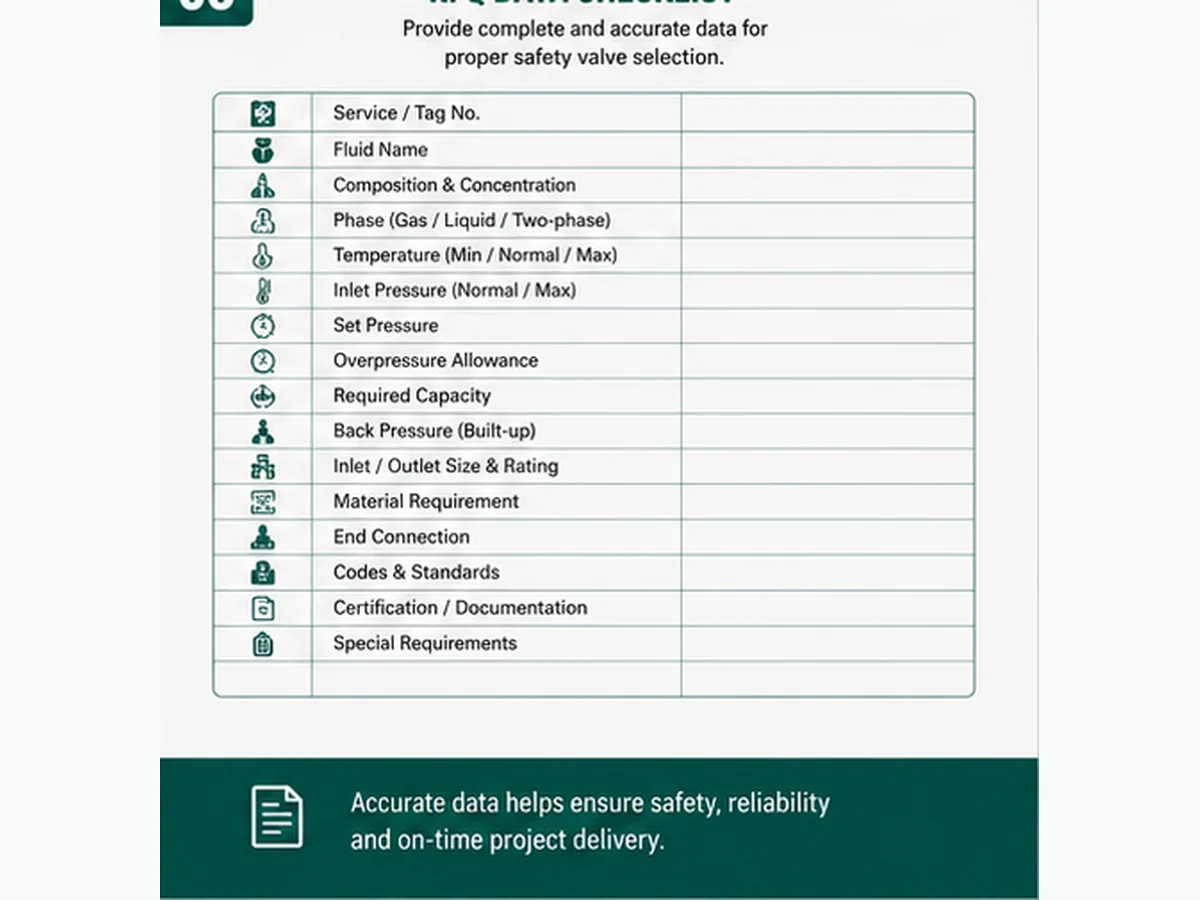
RFQ checklist graphic; final valve selection depends on real service data, manufacturer documentation and project/code review.
A definition becomes an engineering specification only when the protected equipment, relief case and actual exposure are known. The RFQ should state normal, upset, shutdown and relieving conditions where they change phase or chemistry; otherwise the supplier cannot responsibly confirm materials or configuration.
Protected equipment, governing relief scenario and required capacity
Full medium composition, concentration range and contaminants
Normal and relieving phase; dew point, condensate, solids or polymerization risk
Operating pressure, MAWP/design pressure, set pressure, CDTP if applicable and operating margin
Relieving pressure, overpressure/accumulation basis and fluid properties
Normal, startup/shutdown and relieving temperature
Superimposed and built-up back pressure; discharge destination
Inlet/outlet standard, rating, facing/thread and piping layout
Body, bonnet, nozzle, disc, guide, spindle, spring, bellows, gasket and seat requirements
Datasheet, material traceability, test, capacity, inspection and repair-document requirements
Common Mistakes in Corrosion Resistant Safety Valve Selection
| 常见误区 | 风险 | Better check |
|---|---|---|
| Assuming stainless steel is always enough | Localized corrosion, environmental cracking, galling, seal attack or premature failure. | Confirm the corrosion mechanism, exact chemistry, temperature, fabrication condition and every exposed component. |
| Specifying body material only | Nozzle, disc, guide, spindle, spring, bellows, gasket or bolting can remain vulnerable. | Issue a component-level material schedule and exposure map. |
| Ignoring capacity and fluid basis | The valve may fit and resist corrosion but fail to pass the governing relief load. | Compare required capacity with accepted rated capacity for the actual fluid and conditions. |
| Ignoring back pressure and drainage | Unstable operation, corrosive condensate retention, bellows/spring exposure or wrong configuration. | Calculate outlet effects and review vents, drains, support and material. |
| Copying the old valve | Repeats a historic sizing, material, installation or document error after process conditions have changed. | Review current relief scenario, chemistry, capacity, nameplate, as-found data and piping. |
| Treating coating or lining as a universal fix | Damage, disbondment or unprotected functional surfaces can defeat the strategy. | Confirm manufacturer-approved location, preparation, temperature, inspection and repair method. |
替换警告: A corroded valve should not be copied by size, pressure class, set pressure or body material alone. Determine whether the failure came from chemistry, phase change, capacity mismatch, back pressure, deposits, external exposure, maintenance practice or more than one mechanism.
Installation and Discharge Checks in Corrosive Service
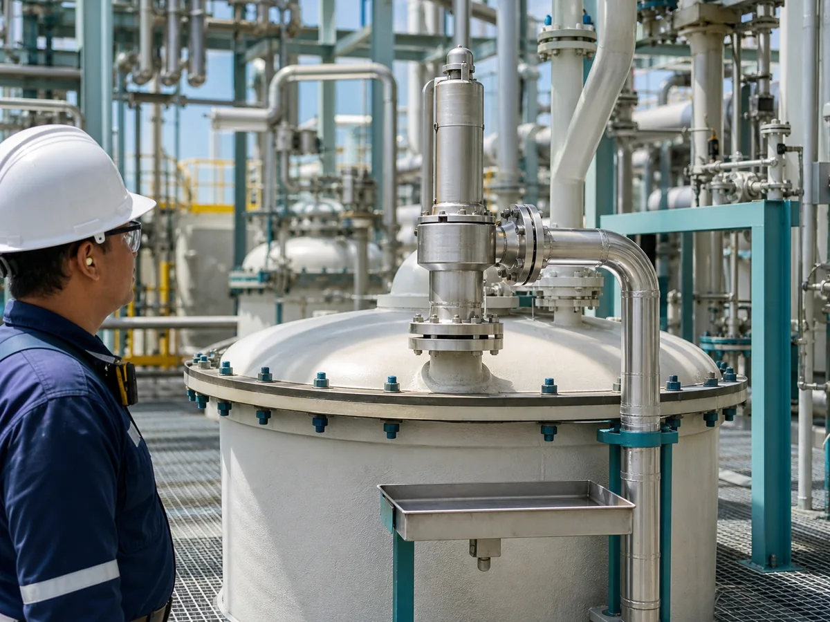
Simplified installation illustration; final installation must follow the selected model instructions, project specification and applicable code.
Mounting orientation, inlet cleanliness and pressure loss
Install the selected valve in the orientation required by the manufacturer, construction code and project. The inlet path should be clean, adequately supported and reviewed for pressure loss, corrosion, deposits and piping strain. Corrosion products or a reduced flow path can impair stability and delivered capacity even when the valve materials are suitable.
Outlet support, drainage, reaction force and corrosive discharge
Support the outlet piping independently and route the discharge to an approved location. Review superimposed and built-up back pressure, reaction force, thermal movement, drains and liquid pockets. Corrosive condensate can attack the outlet, bellows or spring chamber and can restrict discharge if low points are not managed.
Inspection access and risk-based maintenance intervals
Corrosive service can justify shorter or condition-based inspection intervals, but no universal interval applies. Use process history, corrosion mechanism, as-found results, leakage, deposits, material performance, applicable regulation and the site integrity program. Keep access to caps, vents, drains, seals and identification. For general layout checks, review the 安全阀安装指南.
| 应做 | Don’t | 重要性 |
|---|---|---|
| Install in the approved orientation with a short, clean and compatible inlet. | Do not use a long, reduced or corroded inlet without hydraulic and mechanical review. | Inlet loss, deposits and piping strain can affect opening stability and delivered capacity. |
| Support the outlet independently and evaluate reaction loads. | Do not allow a heavy or thermally moving discharge line to load the valve body. | Mechanical load can distort alignment, damage connections and worsen leakage. |
| Provide drainage where condensate or wash liquid can collect. | Do not create unreviewed liquid pockets in the outlet, bonnet vent or sensing path. | Retained corrosive liquid can attack components, freeze, polymerize or restrict movement. |
| Route corrosive discharge and bonnet/bellows vents to safe approved locations. | Do not plug vents, drains or discharge paths as a leakage workaround. | Blocked routing can alter valve behavior or expose personnel and equipment. |
| Provide inspection access and preserve nameplate, seals and traceability. | Do not define a fixed inspection interval without service evidence or regulatory basis. | As-found condition and repeat failure history should drive the maintenance plan. |
Testing, Documentation, and Inspection Requirements
Document requirements should show three separate things: what was selected, what materials and construction were supplied, and how the device was tested or repaired. A set-pressure result does not prove seat tightness or capacity; a material certificate does not prove chemical compatibility; and a repair authorization does not approve the installed relief-system design.
| Document / test item | 所支持的内容 | Buyer note |
|---|---|---|
| Approved valve datasheet | Selected model, opening characteristic, pressure terms, fluid basis, materials, connections and limits. | Use as the controlled technical baseline; record revisions through management of change. |
| Component-level material records | Specified pressure-boundary, trim, spring, bellows, gasket and seat materials where traceability is required. | Define parts and certificate level before quotation; do not request generic “full material certificates.” |
| PMI or other material verification, if required | Verification of identified alloy parts within the project material-verification program. | State parts, method, acceptance and witness requirements; PMI is not a corrosion-compatibility study. |
| Set-pressure test and CDTP basis | Opening adjustment under specified test conditions, including applicable correction basis. | Define test medium, tolerance and applicable standard; it does not establish relieving capacity. |
| 密封性试验 | Leakage performance under the stated method and acceptance basis. | Keep separate from set-pressure and capacity evidence; see API 527 阀座密封性试验. |
| Certified / rated capacity evidence | Relieving capability for the selected device type, configuration and fluid basis. | Compare it with the required relief load; verify manufacturer, model and configuration. |
| As-found / as-left and repair traceability | Condition before work, parts replaced, adjustments, final results, resealing and nameplate status. | Where code repair applies, confirm the authorized repair route and current NBIC/project requirements. |
| Inspection / witness and release scope | Defines hold points, visual/NDE checks, customer or third-party attendance and release records. | State requirements before quotation; do not imply third-party approval from a generic test report. |
| 变更管理记录 | Shows whether medium, throughput, relief scenario, temperature, piping or repair configuration changed. | Revalidate material, capacity and installed-system assumptions after relevant changes. |
Document boundary: Do not assume every corrosion-resistant valve includes PMI, complete traceability, API 527 results, capacity certification, witness inspection or code repair records. Specify the exact evidence required and confirm that it applies to the selected manufacturer, model, configuration and repair scope.
Frequent post-maintenance issue: A valve returns from repair with an acceptable set-pressure result, but the seat continues to leak because pitting remains on the nozzle and the replacement soft seat is not compatible with the process solvent. The correction is component inspection plus the correct seat-tightness and material review. The prevention control is to retain as-found/as-left data, replacement-part traceability and resealing records. This is a composite training example.
更换核实流程
When an existing valve shows corrosion, leakage, sticking, unstable lift or damaged identification, replacement should begin with root-cause and management-of-change review. Copying the old size, set pressure or alloy may reproduce the same failure or preserve an obsolete capacity basis.
Identify the protected equipment and governing relief case.
Confirm the equipment code basis, current process condition, relief scenario and required relieving capacity.
Capture the old valve and installation evidence.
Photograph the nameplate, seals, body, inlet, outlet, bonnet vents, supports, drains, deposits, corrosion and leakage locations.
Define current chemistry and all exposure states.
Check composition range, contaminants, phase, dew point, startup/shutdown, cleaning, relieving temperature and external atmosphere.
Separate material, set pressure and capacity evidence.
Verify required capacity against accepted model-specific capacity; do not infer it from old DN/NPS or a passed set test.
Map component and piping exposure.
Review body, nozzle, disc, guide, spindle, spring chamber, bellows, seals, fasteners, inlet and outlet systems.
Control repair/replacement documents.
Define as-found/as-left data, parts, spring range, material traceability, tests, resealing/nameplate and applicable authorized repair route.
复合工程工况: A chemical-vessel valve has a stainless-steel body, pitted seat and corroded spring chamber. The process datasheet lists only “acid vapor,” but cooling creates condensate with a different concentration. The replacement decision must confirm relief load, set pressure, relieving temperature, condensate chemistry, trim and seat materials, spring-chamber exposure, back pressure, outlet drainage and document scope. The correction is not merely a higher body alloy. This generic training scenario is not a customer case or product-performance claim.
Troubleshooting Corrosion-Related Valve Symptoms
These symptoms are screening clues, not proof of a single corrosion mechanism. Record when the symptom occurs, preserve as-found evidence and review process, piping, sizing and valve condition before repair or replacement.
| 故障现象 | Possible corrosion-related causes | Checks before replacement | 应避免的不安全做法 |
|---|---|---|---|
| 阀座泄漏 | Pitting, particles, deposits, incompatible seat/seal material, galling or condensate attack. | As-found leakage, seat/nozzle condition, chemistry, operating margin, test method and repair history. | Replacing only the body or increasing spring compression. |
| Sticking or delayed opening | Guide/spindle corrosion, galling, crystallization, polymerization, solids or blocked pilot/sensing passages. | Movement, deposits, phase behavior, cleaning history, clearances and component materials. | Assuming set-pressure adjustment alone corrects restricted movement. |
| Flutter or chatter | Oversizing, inlet loss, built-up/superimposed back pressure, unstable process flow, deposits or mechanical load. | Required and rated capacity, inlet/outlet calculations, pressure trend, supports and internal condition. | Changing alloy or valve size without a system review. |
| 回座不良 | Seat damage, corrosion products, unsuitable blowdown behavior, variable back pressure or trapped condensate. | Seat surfaces, pressure trend, blowdown/reseat behavior, outlet drainage and back pressure. | Lapping or polishing without correcting the exposure and piping cause. |
| External corrosion or damaged identification | Marine/chemical atmosphere, washdown, insulation damage, coating failure or galvanic coupling. | External environment, coating/material, bolting, vents, drains, nameplate and inspection history. | Ignoring external parts because the process medium is noncorrosive. |
Corrosion Resistant Safety Valve vs Ordinary Safety Valve
The overpressure-protection function is the same
A corrosion-resistant valve and a standard-material valve must both protect the defined equipment at the correct set pressure and required capacity. Both require suitable pressure rating, stability, back-pressure response, installation and documentation.
The exposure and component-material review is broader
The additional work is to identify corrosion mechanisms and map normal, upset, shutdown, relieving and external exposure to every pressure-boundary, wetted, guiding, sealing and spring-chamber component.
Corrosion resistance does not increase capacity or code status
Changing alloy, seat or coating does not by itself increase effective orifice, rated capacity, allowable set pressure or certification scope. Those properties remain specific to the selected design and evidence.
When to Ask for Engineering Review
Request engineering and corrosion review when the medium is not fully defined; when concentration, phase or temperature varies; when condensation, solids, crystallization, polymerization, chlorides or H₂S may occur; or when external exposure is severe. Provide the protected equipment, governing relief case, pressure terms, required capacity, composition range, phase behavior, temperature profile, back pressure, piping and component-level material requirements.
Replacement requires additional review after corrosion, leakage, sticking, chatter, repeated repair, missing identification, process change or discharge-system modification. Preserve the old datasheet, nameplate, as-found results, photos and repair history. Do not copy the old valve solely because the dimensions match.
常见问题
什么是耐腐蚀安全阀?
该安全阀的压力边界、与介质接触的内部零件及外露功能部件均针对特定腐蚀性介质或环境进行选材。但仍需单独验证整定压力、泄放能力、背压、安装及文件资料。
不锈钢是否总能满足腐蚀性工况的要求?
不。不锈钢是一类合金,其适用性取决于成分、浓度、杂质、相态、温度、制造状态、腐蚀机理及部件所处环境。仅凭阀体材质等级不足以作为判断依据。
选择耐腐蚀安全阀前需要哪些数据?
提供受保护设备、泄放工况、所需泄放量、完整介质成分及范围、相态、杂质、操作与泄放温度、压力参数、背压、管道、部件材料及文件要求。
哪些安全阀部件需要进行腐蚀审查?
可能涉及阀体、阀盖、喷嘴、阀瓣、导向件、阀杆、阀座、弹簧、波纹管、垫片、填料、O型圈、紧固件、阀帽、排放口、入口管道和出口管道。具体检查范围取决于实际接触工况。
涂层或衬里能否使任何安全阀都具有耐腐蚀性?
编号:涂层或衬里仅适用于经批准的表面和工况。它不能替代承压边界、内件、密封面、流通面积、温度、检验、可维修性及制造商设计方面的检查。
耐腐蚀性能能否证明安全阀的排量?
序号 材质适用性、所需泄放量以及特定型号的认证或额定排量需分别核查。连接尺寸、阀体材质和整定压力不能证明排量。
何时应考虑采用波纹管或保护弹簧腔结构?
当出口压力或腐蚀性排放介质可能影响弹簧腔部件时,应予以考虑,但需符合所选型号波纹管材质、温度、疲劳、位移、排放及背压限制。
腐蚀性工况应要求提供哪些文件?
根据项目情况:受控数据表、零部件材质记录、PMI范围、整定压力与密封性结果、额定排量证明、维修前后记录、可追溯性及检验/见证记录。
ISO 15156 / NACE MR0175 是否适用于所有耐腐蚀安全阀?
不。在其适用范围内,它适用于含 H2S 的油气生产和天然气脱硫环境。它不是通用的化学兼容性标准,也不能替代适用的设计规范或项目材料审查。
整定压力试验合格是否能证明材料适用性或泄放能力?
序号:整定压力试验用于验证在规定试验条件下的开启调整。材料适用性、密封性、额定排量及安装系统性能需另行提供证据。
Standards and Selection Boundary
This page explains corrosion-related material and configuration boundaries for safety valves. It does not reproduce copyrighted standards, calculate a relief load, guarantee chemical compatibility or state that a ZOBAI model automatically complies with a jurisdiction. ISO 4126-1 is a product standard, not an application code. API documents have defined refinery/process-industry scopes. ISO 15156 / NACE MR0175 is used only for applicable H2S-containing oil and gas production service. For ZOBAI’s topic overview, see ASME安全阀标准.
Official scope and edition references
Use these official pages to confirm scope and current publication status. The purchased standard, adopted project edition, manufacturer datasheet and local regulatory requirements remain controlling.
- ASME BPVC Section XIII, 2025 — Rules for Overpressure Protection
- API 520 Part I, 10th Edition — Sizing and Selection
- API Standards Plan — current published-edition status for API 520, 521, 526, 527 and RP 576
- ISO 4126-1:2013 with Amendment 1:2016 — safety-valve product standard
- ISO 15156-1:2020 — H₂S-containing oil and gas production material-selection scope
- AMPP — materials selection and design for corrosion control
- National Board NB-18 — pressure-relief-device certification directory
- National Board VR Certificate of Authorization — pressure-relief-valve repair scope
Need a Corrosive-Service Safety Valve Datasheet Review?
Send the protected equipment, relief scenario, required capacity, complete chemistry and concentration range, phase behavior, pressure terms, temperature profile, back pressure, piping layout, component-material requirements and required evidence. Unknown items should be marked “to be confirmed,” not guessed.