了解气体或液体单一相安全阀定径何时不足、两相流计算中有哪些变化,以及在询价前需要核实哪些数据。.

A two-phase relief case should not be sized as an ordinary gas case or ordinary liquid case simply because one phase appears to dominate normal operation. If vapor and liquid coexist at the safety valve inlet—or the fluid changes phase as pressure falls—the sizing method has to represent that actual relieving behavior.
The reason gas-only or liquid-only methods are not a generic substitute for two-phase flow safety valve sizing is not simply that two-phase flow is “more complicated.” A single-phase method represents one phase under defined assumptions; a two-phase calculation has to address phase composition, changing fluid properties, the pressure path, and the mass flux predicted by the selected model.
ISO 4126-10:2024 specifically addresses sizing safety valves and bursting discs for gas/liquid two-phase flow. The practical sequence is therefore to classify the relieving state, choose a method whose assumptions fit that state, establish the required engineering inputs, calculate the required sizing area, and then verify a real valve against the applicable capacity, configuration and project evidence.
For the broader sequence from relief scenario through sizing and capacity verification, see ZOBAI’s 安全阀定径与认证排量指南.
When Does a Relief Case Become a Two-Phase Sizing Problem?
A two-phase sizing problem does not begin only when a visible vapor-liquid mixture is already flowing toward the valve. What matters is the fluid state at the relevant relieving condition and how that state can change as pressure decreases.
Current ISO two-phase sizing guidance recognizes several possible starting conditions. A liquid can enter the device and flash as pressure falls. A near-saturated vapor can move toward condensation. Vapor and liquid can already coexist at the inlet. Gas and liquid may also coexist because gas has been dissolved, generated or otherwise introduced into the liquid phase.
Keeping those paths separate prevents a common mistake: treating two-phase flow 和 flashing liquid as synonyms. Flashing is one route to a two-phase condition, not the definition of every two-phase relief case.
| Relieving condition | First engineering question |
|---|---|
| Gas or vapor remains single-phase | Does the applicable gas/vapor method represent the complete relieving path? |
| Liquid remains single-phase | Does the applicable liquid method remain valid through the relevant pressure reduction? |
| Liquid develops vapor | How will flashing and the resulting vapor-liquid mixture be represented? |
| Vapor develops a liquid phase | Does condensation move the case outside the selected gas-only treatment? |
| Gas and liquid are already present | What phase composition reaches the safety device? |
| Gas and liquid coexist by another mechanism | Does the proposed two-phase model represent that mechanism and state? |
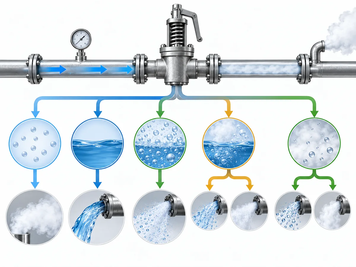
The normal operating description—“gas service” or “liquid service”—is therefore not enough. The engineer needs the relieving-state prediction.
If that cannot yet be answered, choosing a valve orifice is premature.
Why Gas-Only or Liquid-Only Sizing Can Break Down
The limitation of a single-phase method is a model mismatch.
A gas/vapor calculation uses relationships intended for gas or vapor under the assumptions of that method. If a liquid phase develops in a condition the method does not represent, the model no longer describes the complete relieving flow.
Likewise, a liquid calculation describes liquid flow under its applicable assumptions. Once vapor generation or an existing vapor fraction has to be represented by the sizing case, the problem is no longer simply the flow of one liquid phase.
| 定径依据 | What it represents | What must trigger a re-check |
|---|---|---|
| Gas/vapor-only | Single-phase gas or vapor under the applicable method assumptions | Condensation or another relevant liquid phase |
| Liquid-only | Single-phase liquid under the applicable method assumptions | Flashing, vapor generation or an existing vapor fraction |
| Two-phase | Coupled vapor-liquid behavior under a defined two-phase model | A mismatch between model assumptions and the actual relief state |
This does 不 mean that every trace of another phase automatically invalidates every single-phase relationship. The current ISO two-phase framework itself incorporates single-phase limiting relationships and uses certified single-phase gas and liquid discharge coefficients within the broader two-phase procedure.
Another shortcut fails the same test: calculating a gas portion and a liquid portion independently and adding them does not, by itself, demonstrate that the coupled two-phase flow has been modeled correctly.
If the project is being evaluated specifically on an API basis, use ZOBAI’s
API 520 安全阀定径指南
for the broader API-specific sizing workflow. Before applying a specific edition to a project, verify the current publication status through the official
API Standards Plan
and follow the governing project basis.
What Changes in a Two-Phase Flow Calculation?
Once the case is genuinely two-phase, three quantities that are often blurred together need to stay separate: required discharge rate, dischargeable mass flux, 以及 required sizing area.
ISO 4126-10 distinguishes the required mass flow that the relief case must discharge from the mass flux that can pass through a unit flow area under the defined sizing conditions. The sizing procedure then produces the minimum flow area used to select an adequately sized device.
The physical part of the calculation starts with phase composition. In this context, vapor mass quality is a mass fraction: it describes how much of the flowing mass is vapor. It should not be confused with void fraction, which describes how much volume is occupied by the vapor phase.
That distinction matters because the vapor phase can occupy a large share of the volume while representing a very different share of the total mass.
1. Establish the required relieving load
The relief scenario determines what mass flow the protected system needs to discharge.
2. Define the relieving fluid state
The model needs sufficient information to represent the vapor-liquid composition and the relevant change in properties as pressure falls.
3. Determine the applicable two-phase mass flux
The selected model predicts how much mass can pass per unit flow area under the sizing condition.
4. Determine the required sizing area
The required load is then matched to the dischargeable mass flux.
所需泄放量
→ relieving fluid state and phase composition
→ two-phase model and pressure path
→ critical or subcritical mass flux
→ required sizing area
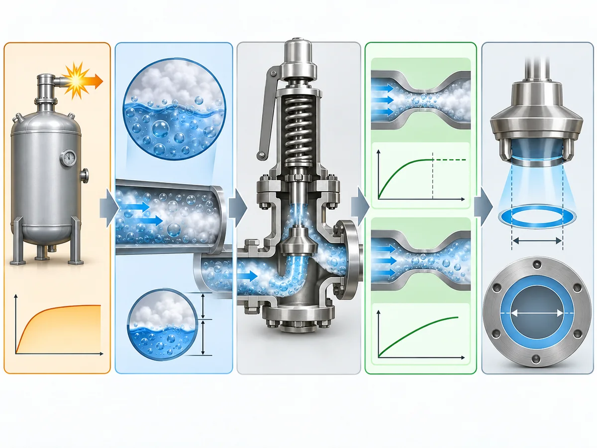
Critical flow is part of that calculation, but it should not be reduced to the familiar ideal-gas picture of “sonic flow.” For the defined sizing condition, the critical state is reached when further reduction of downstream pressure no longer increases mass flow. The critical location also should not be assumed to be identical in every device or installed system.
Two-phase safety valve sizing is therefore not simply a longer gas equation or a corrected liquid equation. The calculation has to represent a changing fluid state and the flow behavior that follows from the chosen model.
How Should Engineers Choose a Two-Phase Sizing Method?
Choose the method from its assumptions and applicability, not from the acronym printed on a spreadsheet.
ISO 4126-10:2024 uses an omega-parameter-based framework with treatment for thermodynamic non-equilibrium. The current edition also extends the procedure to address factors such as phase slip and pressure effects around the safety device. The wider process-safety literature, including DIERS work, considers multiple two-phase approaches rather than one universal equation.
| Question to resolve | Why it changes the decision |
|---|---|
| What reaches the safety-device inlet? | Already mixed flow, flashing liquid and condensing vapor do not start from the same condition. |
| Is thermodynamic equilibrium an acceptable assumption? | The calculation can change if phase generation does not follow the assumed equilibrium path. |
| Does non-equilibrium behavior need to be represented? | Delayed boiling or condensation can change the modeled mass flux. |
| Does the selected method’s treatment of phase slip fit the case? | Different models do not necessarily make identical assumptions about phase movement. |
| Is the required property basis available over the pressure path? | A sophisticated equation is still unreliable if its thermodynamic inputs are not defensible. |
| Is flow critical or subcritical? | The result affects dischargeable mass flux. |
| Do relevant inlet/outlet losses or back pressure affect the method or device? | Installed-system pressure conditions can alter the sizing or final device assessment. |
| What project standard and edition governs? | A technically possible method is not automatically the project-required method. |
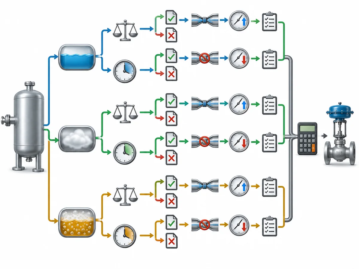
For that reason, phrases such as “the conservative method” require care. The evidence does not support a universal ranking in which one two-phase method always produces the safest or largest result across all fluids and relief conditions.
A similar caution applies to saying that two-phase flow “always needs a larger valve.” A defined comparison can produce a larger required area, but that should not be expanded into a rule for every fluid, relief scenario and calculation basis.
These are engineering stop conditions, not regulatory classifications. Their purpose is to prevent an apparently precise valve area from being produced from an undefined physical model.
For projects governed by ISO, use ZOBAI’s
ISO 4126 Safety Valve Standard Guide
for the broader relationship between ISO 4126 parts rather than turning this page into a standards commentary.
DIERS provides additional process-safety context on emergency relief and two-phase venting methodology through
AIChE/CCPS.
What Data Must Be Defined Before Sizing or Sending an RFQ?
A two-phase safety valve RFQ should start with the relief case, not the requested valve size.
The exact data set depends on the fluid, selected method and governing project requirements. The information should nevertheless be sufficient to establish four things: what must be relieved, what state the fluid is in, what calculation basis applies, and what candidate-valve evidence has to be checked.
确定泄放工况
Provide enough process information to identify:
- the protected equipment or pressure boundary;
- the credible relief scenario;
- the required relieving-load basis;
- the relieving or sizing pressure; and
- the relieving or sizing temperature.
A bare flow rate is not a substitute for the relief scenario because the scenario affects both the required load and the expected fluid state.
Define the fluid state, not just the fluid name
“Hydrocarbon,” “water,” “process liquid” or “gas” may not tell the engineer enough for a two-phase calculation.
Depending on the selected method, relevant information can include fluid composition or identity, inlet phase state, vapor mass quality or other phase information, density or specific-volume data, and the thermodynamic or flash-property basis required to represent the relieving path.
The key qualifier is depending on the selected method. Not every two-phase procedure requires an identical property-input list.
Include relevant installed-system pressure conditions
Where they affect the sizing procedure or candidate device, provide downstream pressure or back pressure and the relevant inlet/outlet pressure-loss information.
This does not mean every supplier inquiry needs a complete discharge-network study. It means significant system conditions should not be omitted when the selected procedure or candidate valve depends on them.
For a deeper installed-system discussion, use ZOBAI’s
Back Pressure in Spring-Loaded Safety Valves Guide.
If a candidate valve already exists, submit its real product data
The review then needs to connect process-side requirements to actual valve documentation. Relevant fields can include applicable flow area, capacity or discharge-coefficient basis, pressure-temperature limits, construction and material information, configuration, back-pressure information, and whatever certification or test documentation the project requires.
Use the following table as a practical RFQ responsibility map, not as a regulatory or contractual allocation. Actual responsibilities and approval authority must follow the governing project requirements and agreed project scope.
| Information | Typical evidence owner for RFQ preparation |
|---|---|
| Credible relief scenario | Process / project engineering |
| 所需泄放量 | Process engineering |
| Fluid composition and relieving state | Process engineering |
| Thermodynamic/property basis | Process engineering / validated property basis |
| Governing sizing method | Responsible project engineering |
| Installed back-pressure condition | Process / mechanical engineering |
| Candidate valve data | Valve manufacturer |
| Candidate capacity or coefficient evidence | Valve manufacturer / certification documentation |
| Product configuration and limits | Manufacturer + project engineer |
| Final technical acceptance | Responsible project authority under the governing project requirements |
A supplier inquiry containing only pressure, temperature, a flow figure and a preferred connection size can therefore leave important engineering questions unanswered.
ZOBAI’s
engineering review page
is the appropriate next-step owner for working conditions, drawings, datasheets and project specifications once the relief case is sufficiently defined.
What Does the Calculated Area Not Prove About the Safety Valve?
The required sizing area is an engineering result. It is not a product approval.
A defensible selection keeps each evidence layer separate.
Credible relief scenario
→ required relieving load
→ applicable two-phase model
→ dischargeable mass flux
→ required sizing area
→ candidate safety valve
→ applicable capacity or coefficient evidence
→ pressure-temperature, material and configuration checks
→ installed-condition review
→ project acceptance
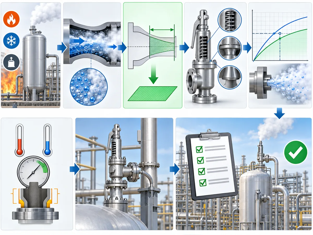
ISO 4126-10 defines sizing area as the minimum flow cross-section resulting from the sizing procedure that is then used to select an adequately sized safety device. The same two-phase framework can use certified gas and liquid discharge coefficients within the calculation.
| Evidence layer | 其确立的内容 | What it does not establish alone |
|---|---|---|
| 所需泄放量 | The process demand for the governing case | Candidate valve capacity |
| Two-phase calculation | Mass flux and required sizing area under the selected basis | Complete product suitability |
| Capacity / discharge-coefficient evidence | Device performance within its documented basis | Universal suitability for every two-phase service |
| Pressure-temperature and construction data | Product limits and configuration | Correctness of the original process relief load |
| Installed-condition review | Compatibility with actual inlet/outlet conditions | The relief scenario itself |
| Project/code review | Acceptance against the governing project basis | Missing calculation or product evidence |
Connection size, flange class or an apparently suitable catalog model cannot close that evidence gap. ZOBAI has a separate
guide to certified relieving capacity versus connection size
for the detailed capacity distinction.
For the broader product-selection decision beyond sizing, use the
安全阀选型指南.
A two-phase relief problem therefore has to be solved in the correct order: establish the relieving state, choose a method whose assumptions fit that state, calculate the required duty and area, and then verify a real valve against the applicable product and project evidence. When one of those links is missing, a more precise-looking number does not make the selection more reliable.