A jacketed safety valve can keep the valve body within a required temperature range, but that does not automatically mean the connected outlet piping is under the same thermal control. The jacket protects only the physical region it actually covers. Once the process medium passes beyond that heated region, the discharge path has its own …


A jacketed safety valve can keep the valve body within a required temperature range, but that does not automatically mean the connected outlet piping is under the same thermal control. The jacket protects only the physical region it actually covers. Once the process medium passes beyond that heated region, the discharge path has its own exposure to ambient conditions, insulation, pipe geometry and any separate outlet heat tracing or discharge-line heat-tracing system.
That distinction matters only when temperature can materially change the behavior of the medium or the condition of the discharge path. In some services, cooling may increase viscosity, cause freezing or solidification, promote crystallization or precipitation, or leave material that does not drain readily. In other services, the same degree of cooling may have little practical effect. This is why outlet tracing should be treated as a service-specific thermal-boundary decision, not as an automatic accessory to every jacketed safety valve.
The key engineering question is not simply, “Is the valve jacketed?” It is:
Where does temperature maintenance actually need to end for this medium, this relief scenario and this discharge arrangement?
The Jacketed Valve and the Outlet Do Not Automatically Share the Same Thermal Boundary
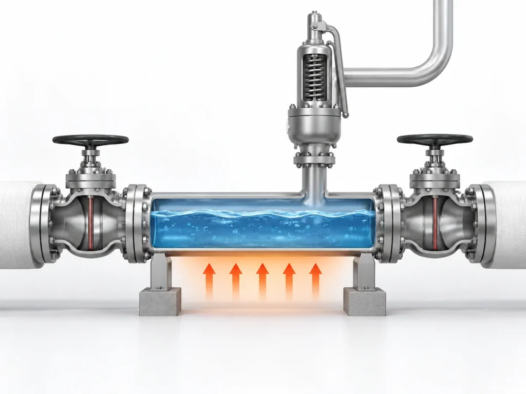
A jacketed safety valve is normally selected because temperature control around the valve itself is important to the service. Depending on the design, the jacket may cover the valve body and may extend around other portions of the valve, but the exact heated boundary is product-specific and should be confirmed from the applicable drawing or product data.
The downstream piping begins a different thermal problem. Once the medium moves into a section that is no longer jacket-heated, its temperature is influenced by the pipe material and diameter, exposed length, insulation, ambient conditions, fittings, local heat losses and any separate tracing arrangement. A short insulated spool inside a warm process area may behave very differently from a longer discharge line exposed to low ambient temperature.
The end of the valve jacket is a product boundary. It is not automatically the end of the temperature-maintenance requirement for the process.
A jacketed valve does not automatically mean that the outlet must be traced. If the discharged medium remains acceptably fluid and stable throughout the relevant downstream conditions, additional temperature maintenance may not be required for that thermal reason. The tracing decision depends on what temperature change actually does to the service.
What Can Change When the Outlet Cools
Cooling by itself is not the failure mechanism. The important question is whether cooling moves the medium into a temperature range where its physical behavior changes enough to affect the discharge path.
For a temperature-sensitive liquid, a lower temperature may significantly increase viscosity. In another service, cooling may cross a freezing or solidification boundary. Other media may crystallize, precipitate solids, condense or form deposits under particular combinations of temperature, composition and pressure. These mechanisms are not interchangeable, and none should be assumed without service-specific information.
Outlet cooling can come from more than ambient heat loss
Ambient exposure is one source of outlet cooling, but it is not the only one. In some services, pressure reduction, flashing or gas expansion through the relief path can also reduce fluid temperature. That auto-refrigeration effect may matter where the medium can freeze, form hydrates, condense, or deposit solids at the lower temperature.
For that reason, the relevant outlet temperature should come from the actual relieving and winterizing case, not from the normal upstream process temperature alone. Whether this mechanism matters depends on fluid composition, phase behavior, pressure change and the discharge arrangement.
The assessment starts with the medium: temperature change → medium response, not with the valve.
If the medium remains fully flowable over the expected temperature range, an unheated outlet section may not create a thermal problem. If cooling instead causes material to become highly viscous, form solids or accumulate in low points, the downstream condition deserves much closer review.
A medium change is not yet the same as a restriction
Even when cooling changes viscosity or produces solids, that does not automatically mean the discharge line has become hydraulically restrictive. The quantity of retained material, available flow area, pipe geometry, relieving rate and actual fluid properties all matter.
Only when the resulting condition materially increases resistance through the discharge path does it become a pressure-loss issue.
A change in medium behavior does not by itself establish a back-pressure problem: outlet cooling ≠ built-up back pressure.
outlet cooling
→ may change medium behavior
→ may create accumulation or restriction
→ if the restriction materially increases pressure loss, built-up back pressure can increase
→ may change medium behavior
→ may create accumulation or restriction
→ if the restriction materially increases pressure loss, built-up back pressure can increase
In ISO 4126-7 terminology, built-up back pressure is the outlet pressure generated by flow through the safety valve and its discharge system. Whether an increase in that pressure materially changes safety-valve operation then depends on the valve configuration, the amount and variability of back pressure, manufacturer limits and the applicable relief-system design basis.
An untraced outlet should not be assumed to make a valve unstable or cause a particular performance problem. The hydraulic consequence has to be established separately.
The governing thermal condition may not be the full-flow relief event
Maximum relieving-flow temperature is not always the governing thermal condition.
Using the maximum relieving-flow temperature as the sole thermal basis may be appropriate in some systems, but it is not universal. A discharge line can experience different thermal states during startup, shutdown, standby, ambient exposure, smaller relief events and after a relief event when material remains in part of the piping.
A credible leakage, simmering or other small-flow case can also govern the thermal review. A small intermittent or continuous leak can enter an outlet that has cooled toward the winterizing temperature, and some project practices specifically check whether that leaking fluid would freeze, congeal or become excessively viscous under those conditions. This case should be evaluated where it is credible; it should not be assumed for every valve or service.
Consider a system that is normally hot but has long standby periods. The valve body may remain heated by its jacket while the connected outlet section approaches ambient temperature. If a temperature-sensitive fluid enters that cold section during a later event, the initial pipe condition can matter even though the flowing medium itself is hot.
In another service, continuous or repeated flow may keep the outlet sufficiently warm without separate tracing. The controlling condition has to be identified from the actual process rather than assumed from one operating point.
What Determines Whether the Outlet Actually Needs Tracing
The tracing decision becomes much clearer when it is treated as a set of engineering variables instead of a yes-or-no rule attached to the valve type.
| Decision factor | 重要性 | What should be verified |
|---|---|---|
| 介质特性 | Determines whether cooling changes viscosity, phase, solubility or solids formation | Relevant temperature-property data and composition |
| Required temperature condition | Defines the temperature range needed to maintain acceptable flow behavior | Project or process maintain-temperature basis |
| 泄放温度 | Establishes the temperature entering the discharge path during the applicable relief case | Relief calculation / process data |
| Standby, startup and shutdown conditions | The coldest or most restrictive condition may occur outside normal operation | Relevant operating states |
| Minimum ambient temperature | Affects heat loss and cold-start condition | Site design data |
| Jacket coverage | Defines where valve-side heating actually stops | Valve drawing or product data |
| Outlet geometry | Length, diameter, fittings and exposed surface affect heat loss and hydraulic behavior | Actual piping layout |
| Insulation | Reduces heat loss but does not generate heat | Type, thickness and continuity |
| 排液与低点 | Retained material may experience extended cooling | Piping arrangement and drains |
| 排放去向 | Header pressure and downstream conditions affect overall relief-system behavior | Open discharge, closed system or header data |
| Heat-tracing basis | Determines whether the proposed system can maintain the required temperature | Heat-loss calculation and tracing design |
| Project requirements | May impose additional design or documentation requirements | Applicable project specification |
No single item in this table decides the question by itself.
For example, knowing that a product begins to crystallize below a certain temperature still does not establish the tracing design. The engineer also needs to know whether the relevant outlet section can actually reach that temperature, how long it remains there, whether insulation is present, whether material remains in the pipe and what temperature the tracing system is expected to maintain.
Likewise, knowing that the site has a low minimum ambient temperature does not prove that tracing is required. If the medium is not sensitive to that temperature or the relevant section remains adequately warm for other reasons, the design conclusion may be different.
A four-step tracing decision path
- Screen the medium. Determine whether, within a credible temperature range, it can become unacceptably viscous, freeze, solidify, crystallize, condense, form hydrates or otherwise create a restriction.
- Screen the outlet temperature. Determine whether the outlet can actually reach that range during relief, leakage or simmering, standby, startup, shutdown or post-relief conditions, including ambient heat loss and any relevant expansion or flashing cooling.
- Check passive heat retention. Determine whether the actual pipe geometry, retained process heat and insulation are sufficient to keep the outlet above the required maintain-temperature basis without active tracing.
- Design and verify separately. If active temperature maintenance is still required, perform the heat-loss and tracing design, then separately verify drainage, outlet hydraulics, back pressure, supports and safe discharge.
Use this sequence for screening and specification. The project heat-loss calculation and relief-system hydraulic analysis remain separate requirements.
There is no universal tracing length
A fixed instruction such as “trace the first one metre after the valve” is not a reliable general rule.
Required tracing coverage depends on the thermal duty. Pipe diameter, length, material, ambient temperature, insulation, fittings, equipment surfaces and the required maintain temperature all influence heat loss. A short uninsulated metallic outlet can present a different duty from a longer, well-insulated discharge line.
The maintain temperature also should not be chosen simply because the valve or upstream process operates at a particular temperature. The relevant target is the temperature needed to keep the medium within an acceptable condition for the actual service, while also respecting any product or material temperature limits.
Representative engineering scenario
Consider a jacketed safety valve protecting equipment that contains a temperature-sensitive liquid. The valve jacket maintains the valve region at the required process condition, but the outlet piping leaves the heated area and passes through a colder location.
The decision should not be reduced to: jacketed valve → trace the outlet.
A more reliable sequence is:
- Confirm where the valve jacket actually ends.
- Determine the temperature-sensitive behavior of the medium.
- Identify the relevant thermal condition during standby, startup, relieving and post-relief periods.
- Estimate or calculate the temperature condition of the outlet section.
- Determine whether that condition could create unacceptable viscosity, phase change or solids behavior.
- If temperature maintenance is needed, design the tracing and insulation for that thermal duty.
- Independently verify the outlet hydraulics, drainage and back-pressure conditions.
This sequence is illustrative, not a recorded customer case or a universal tracing specification.
What Outlet Tracing Cannot Fix
Outlet tracing can address a thermal problem. It cannot convert an otherwise unsuitable discharge system into an acceptable one.
If the discharge piping is undersized, unnecessarily restrictive or connected to a system with excessive downstream pressure, heat tracing does not correct the hydraulic design. If the piping traps liquid because of poor drainage or unsuitable low points, tracing does not eliminate the need to review the piping arrangement . It also does not establish that reaction forces, supports or safe discharge requirements have been addressed.
Different controls solve different problems
| Control | What it does | What it does not replace |
|---|---|---|
| Heat tracing | Adds heat to maintain a required temperature condition where the thermal duty justifies it. | Does not correct undersized or overly restrictive discharge piping and does not by itself prove acceptable back pressure. |
| Insulation | Reduces heat loss and helps preserve available process or tracing heat. | Does not generate heat and does not correct retained liquid, poor drainage or an unsuitable piping layout. |
| Slope and drainage | Reduce the opportunity for liquid or residual material to remain in low points and cool for extended periods. | Do not maintain temperature and do not replace tracing where active heat input is actually required. |
| Outlet hydraulic design | Addresses piping size, layout, pressure loss and the resulting back-pressure condition for the relief system. | Does not keep a temperature-sensitive medium warm or prevent phase change and solids behavior by itself. |
The same boundary applies to safety-valve capacity. Adding heat tracing does not increase or prove the valve’s certified relieving capacity. Capacity remains dependent on the selected valve, orifice or flow area, service conditions and the applicable manufacturer or certification basis.
背压 must also remain a separate check. If a temperature-related deposit reduces the effective flow path enough to increase pressure loss, built-up back pressure may rise. But the size of that effect cannot be inferred from the presence of deposits alone. It requires the actual relieving flow, outlet geometry, fluid properties and downstream pressure conditions.
Similarly, the resulting effect on the safety valve depends on the design being used. A conventional spring-loaded valve, a balanced bellows design and a pilot-operated valve do not have identical back-pressure behavior or limitations. Outlet tracing therefore should never be presented as a substitute for selecting and verifying the correct relief-device configuration.
What to Verify Before Specifying Outlet Tracing
A useful tracing specification should begin with service information rather than with a standard tracing temperature or a fixed length of pipe.
Before deciding the outlet treatment, confirm the following.
Medium and thermal behavior
Identify the medium, phase and composition closely enough to understand the temperature-dependent behavior that matters to the discharge path. Depending on the service, the relevant concern may be viscosity, freezing, solidification, crystallization, precipitation, condensation or another documented limitation.
Only properties that can change the tracing decision need to be established.
Relevant temperatures and operating states
Confirm the normal operating temperature and the relieving temperature, but also consider the conditions that may leave the outlet cold before a relief event. Minimum ambient temperature, startup, shutdown and standby conditions may be important where the process is intermittent.
A tracing design also needs a defined maintain-temperature basis. That temperature should come from the process requirement and validated medium behavior, not from a generic rule for jacketed valves.
Valve and piping boundary
Confirm the actual jacket coverage from the applicable product information. Then review the outlet diameter, length, material, fittings, insulation, exposed sections, low points, drainage and discharge destination.
This establishes where separate thermal control may be needed and provides the information required for a heat-loss or tracing design.
Relief-system conditions
Confirm the discharge arrangement and relevant back-pressure conditions independently of the tracing decision.
If the valve discharges into a closed header, existing superimposed back pressure and the additional built-up back pressure during relieving may both be relevant. If a thermal restriction is considered credible, its potential hydraulic consequence must be evaluated rather than assumed.
Tracing and insulation design
If the assessment shows that the outlet requires temperature maintenance, the tracing system should be designed for the actual thermal duty.
That normally means considering the required maintain temperature, minimum ambient condition, pipe geometry, insulation, heat loss, startup requirement and any equipment or fitting allowances. The choice between steam tracing and electric heat tracing should follow the project conditions and available utilities; neither method should be treated as universally preferable.
The final specification should also make the responsibility boundary clear. The valve manufacturer may need to confirm the jacket configuration and product temperature limits, while the process, piping or heat-tracing engineer may own the downstream thermal and piping design. Project responsibilities should be defined rather than assumed.
Pre-Specification Checklist
Before releasing the tracing requirement, verify that the project has enough information to answer these questions:
- What medium and phase can enter the discharge line?
- What temperature-dependent behavior creates the thermal concern?
- What is the relevant operating or relieving temperature?
- What are the important startup, shutdown or standby conditions?
- What minimum ambient condition applies?
- Where does the valve jacket actually end?
- What outlet piping remains outside that heated region?
- Is that piping insulated?
- Can material remain in low points or poorly drained sections?
- Where does the valve discharge?
- What back-pressure conditions apply?
- What temperature must the downstream piping actually maintain?
- Has the tracing duty been checked against the real pipe and insulation arrangement?
- Which requirements come from the process design, valve manufacturer and project specification?
If those questions cannot yet be answered, do not assign a tracing temperature or length. Close the missing engineering inputs first.
Safety and code boundary
API 520 第 II 部分 addresses pressure-relief-device installation, while API 521 addresses pressure-relieving and depressuring systems, including disposal-system engineering. ISO 4126 provides additional safety-device terminology and technical framework. Those scopes are relevant to the wider relief-system review, but their names alone do not establish a universal requirement to heat-trace the outlet of every jacketed safety valve.
The applicable edition, project specification, process conditions and valve/manufacturer data still have to be confirmed.
Final design still requires the project relief calculation, piping review, manufacturer data and the applicable jurisdiction-specific code assessment.
常见问题
Does every jacketed safety valve need outlet heat tracing?
No. A jacketed valve only establishes the heated boundary of the valve itself. Separate outlet tracing is justified when the actual service and downstream conditions show that temperature loss could make the medium unacceptably viscous, cause phase change or solids formation, or otherwise create a credible restriction in the discharge path.
Where should outlet tracing start and stop?
There is no universal fixed length. The required coverage depends on where the valve jacket ends, the outlet geometry, insulation, ambient condition, the medium’s temperature-dependent behavior and the maintain-temperature basis for the service. The tracing boundary should come from the thermal duty rather than from a generic distance after the valve.
Can insulation replace heat tracing on the outlet?
Not when active heat input is required. Insulation reduces heat loss, but it does not generate heat. In some services, insulation and retained process heat may be sufficient to keep the outlet within the required temperature range; in others, active tracing is still needed.
Can outlet cooling increase built-up back pressure?
It can contribute only through a conditional chain. Cooling may change the medium, that change may create deposits, retained material or another restriction, and the restriction must materially increase discharge-line pressure loss before built-up back pressure increases. Cooling by itself is not the same as a back-pressure problem.
Can outlet tracing correct undersized or poorly arranged discharge piping?
No. Tracing addresses temperature maintenance. It does not correct an undersized or overly restrictive outlet, poor drainage, unsuitable low points, excessive downstream pressure, support problems or an otherwise unacceptable relief-system layout. Those issues require separate piping and hydraulic verification.
What information should be confirmed before specifying outlet tracing?
Confirm the process medium and phase, relevant temperature-dependent behavior, normal and relieving temperatures, minimum ambient condition, startup/shutdown/standby cases, actual valve-jacket coverage, outlet piping geometry, insulation, drainage and low points, discharge destination, back-pressure conditions, and the required maintain temperature. Those inputs determine whether tracing is needed and, if it is, the thermal duty it must satisfy.
Need help reviewing the outlet thermal boundary?
For an engineering review, provide the process medium and phase, normal and relieving temperatures, minimum ambient condition, set pressure and relevant relief scenario, the jacketed-valve configuration, available jacket drawing, outlet piping arrangement, discharge destination, insulation and any existing tracing or project requirements.
With those inputs, the discussion can focus on the actual question: where temperature maintenance needs to continue, and which parts of the relief-system design still require separate verification.
工程师咨询