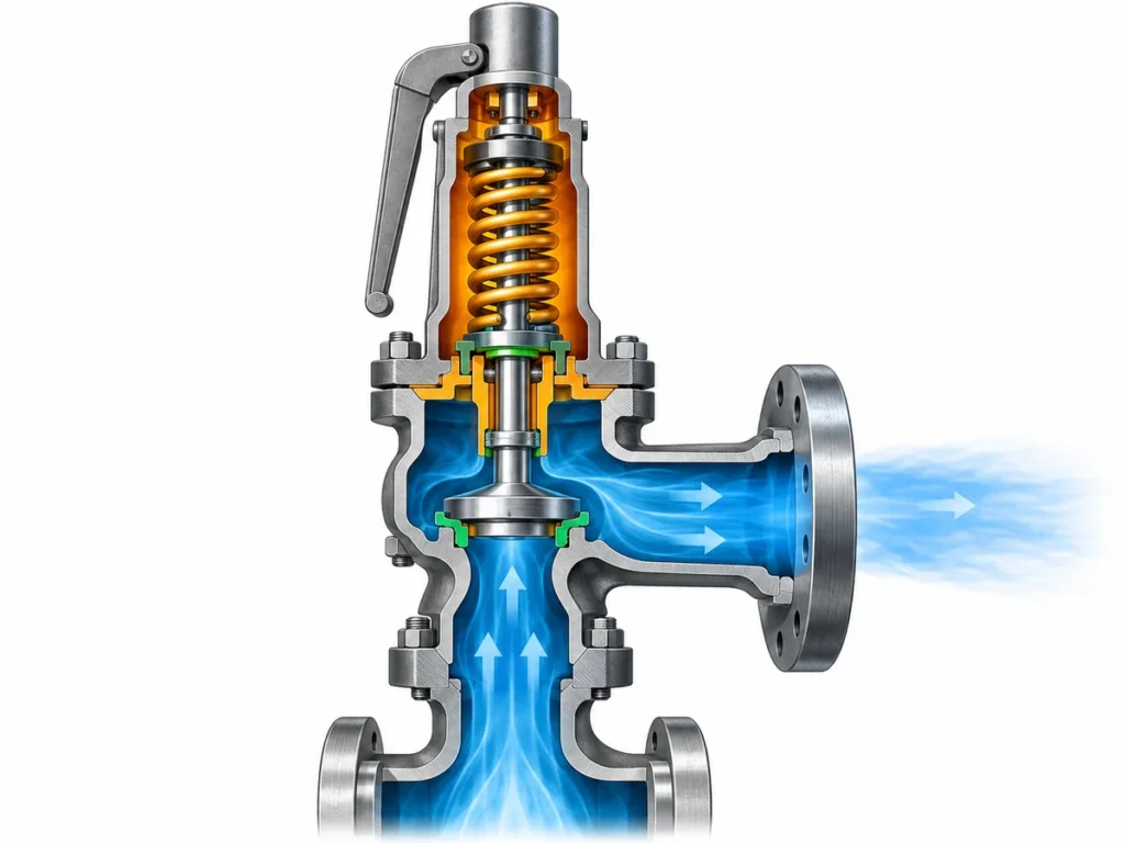
Revise como múltiplas válvulas de segurança de caldeira são escalonadas por pressão de ajuste e como a capacidade documentada, a localização protegida e os dados de verificação afetam a alocação de capacidade.

O escalonamento da pressão de ajuste das válvulas de segurança de caldeira não deve ser baseado apenas na ordem de abertura. Múltiplas válvulas de segurança de caldeira não devem ser escalonadas por pressão de ajuste e depois verificadas apenas somando capacidades nominais. A revisão deve começar pela base de pressão governante da caldeira e pela demanda requerida de alívio de vapor, e então aplicar o arranjo de pressão de ajuste permitido e creditar cada válvula apenas com base em uma capacidade documentada ou certificada que seja válida para aquela válvula, sua pressão de ajuste, condição de vapor e localização protegida.
Essa distinção é importante porque o escalonamento da pressão de ajuste e a alocação de capacidade estão relacionados, mas desempenham funções diferentes. O escalonamento define parte do arranjo de proteção de pressão. A alocação de capacidade determina como a demanda requerida de alívio é efetivamente coberta. Uma lista convincente de pressões de ajuste não prova capacidade suficiente, e uma grande soma aritmética de capacidades de catálogo não prova que as contribuições individuais sejam válidas para o arranjo instalado.
Base de Pressão de Ajuste e Capacidade das Válvulas de Segurança de Caldeira
Antes de atribuir percentuais ou parcelas de capacidade a válvulas individuais, defina o que o sistema completo de proteção deve realizar.
Para uma caldeira a vapor, isso normalmente significa identificar a caldeira ou seção de caldeira protegida, a base de pressão usada para proteção, a demanda máxima de alívio de vapor que deve ser atendida e as regras do código ou do projeto que controlam o arranjo. Esses dados de entrada pertencem ao topo da revisão, pois todas as decisões posteriores dependem deles.
Os campos de pressão também precisam permanecer distintos. A pressão normal de operação não é a mesma grandeza que a pressão máxima de trabalho admissível ou outro limite de projeto governante. A pressão de ajuste não é a pressão de alívio. E nenhuma dessas pressões é, por si só, um valor de capacidade de alívio.
A mesma separação se aplica ao lado da capacidade. A caldeira tem uma capacidade de alívio requerida. Cada válvula possui uma capacidade documentada ou certificada sob condições definidas. A tarefa de engenharia é demonstrar que as capacidades legitimamente creditáveis na instalação atendem à exigência governante da caldeira.
Um registro inicial útil deve conter, no mínimo:
- a caldeira ou seção protegida;
- o código aplicável, edição adotada, jurisdição ou base do projeto, quando conhecidos;
- a pressão governante ou MAWP;
- a pressão normal de operação, quando relevante para a análise;
- a carga requerida de alívio de vapor ou a máxima geração de vapor utilizada no projeto;
- a localização de cada válvula de segurança;
- a identificação da documentação utilizada para comprovar a pressão de ajuste e a capacidade de cada válvula.
Esta ordem evita um erro comum: começar pelas válvulas que estão disponíveis e tentar ajustar as capacidades de catálogo delas a uma demanda requerida que ainda não foi claramente estabelecida.
A demanda requerida não é a vazão normal de vapor
Uma caldeira pode passar a maior parte de sua vida operacional abaixo de sua condição máxima de geração de vapor. Isso não faz da vazão normal de operação a base automática para a proteção contra sobrepressão.
A demanda de alívio requerida deve vir do projeto governante da caldeira e da base normativa. Dependendo das regras aplicáveis, essa base pode estar vinculada à capacidade máxima de geração de vapor ou evaporação, à entrada de calor ou a outro método aprovado. Nenhum método único deve ser tratado como fórmula universal, porque o código governante e a construção da caldeira não foram fixados para todos os leitores.
A regra prática é mais simples: estabelecer primeiro a demanda requerida e, em seguida, comparar o arranjo das válvulas de segurança com ela.
Definir pressões de ajuste em estágios sem tratar a ordem de abertura como prova de capacidade
Quando várias válvulas de segurança protegem o mesmo sistema de caldeira, atribuir a elas pressões de ajuste diferentes pode criar uma resposta escalonada intencional. A válvula com ajuste mais baixo é posicionada para responder a um limiar de pressão menor, enquanto válvulas adicionais podem ter ajustes permitidos mais altos.
Mas uma lista escalonada de ajustes de placa de identificação é apenas uma parte do projeto de proteção contra pressão.
A relação permitida entre os ajustes depende do código. Por exemplo, as regras atuais da Virgínia e de Maryland para caldeiras de potência existentes ilustram uma abordagem jurisdicional dos EUA: uma ou mais válvulas de segurança são ajustadas em ou abaixo da MAWP, válvulas adicionais podem ser ajustadas dentro de uma porcentagem limitada acima da MAWP, e a faixa geral de ajustes também é limitada. Essas mesmas regras aplicam um critério definido de elevação de pressão ao avaliar se a capacidade de alívio instalada é suficiente.
Esses valores são úteis para entender o padrão de engenharia, mas são not universal design defaults. Another jurisdiction, a different boiler category, or a different adopted edition may impose a different requirement. The schedule therefore needs a field for the governing source rather than a hard-coded “standard staging percentage.”
There is a second reason not to over-interpret the nameplate settings: two values on a schedule do not, by themselves, prove the exact dynamic sequence in every operating transient. Actual valve behavior also depends on the valve design, setting tolerance, pressure development, installation, and system response.
For the purposes of a boiler safety-valve schedule, the safer interpretation is:
Set pressure defines the intended pressure threshold and must satisfy the governing pressure rules. It does not independently demonstrate how much steam the valve can relieve or prove the adequacy of the complete arrangement.
This is where pressure staging and capacity allocation begin to interact. Changing the set pressure can also change the relieving-pressure basis under which a steam capacity is established. A capacity number should therefore not be detached from the setting and certification basis that supports it.
Allocate Capacity Valve by Valve on the Correct Basis
Once the boiler’s required duty and the permitted set-pressure arrangement are defined, the engineer can turn to the capacity allocated to each valve.
The first question is not “What percentage should each valve carry?” It is:
What capacity can this particular valve legitimately contribute to this particular protected arrangement?
That contribution needs an identifiable basis.
For steam safety valves, recognized certification data can tie relieving capacity to factors such as the valve design identity, marked set pressure or valid set-pressure range, code designator, steam condition, effective flow area, and the relieving-pressure basis used for certification. National Board NB-18 documentation is a useful example of why capacity is not a free-standing catalog value: the certified steam-capacity methodology explicitly relates capacity to marked set pressure, relieving pressure, code basis, and steam condition.
This creates an important review sequence:
- establish the required boiler relieving duty;
- identify each valve;
- confirm the valve’s set pressure;
- identify the applicable capacity document or certification basis;
- confirm that the documented capacity applies to the relevant steam and pressure conditions;
- determine whether that capacity is creditable in the installed location;
- only then aggregate the allowed contributions.
Capacity arithmetic is not capacity proof
Suppose a schedule contains three valves with three capacity values. Adding the three numbers is mathematically easy. The engineering question is whether the three numbers are comparable and creditable.
A valve capacity taken from a different set-pressure condition, a different certified design, or a different steam condition cannot automatically be carried into the current schedule. The same caution applies when a number comes from a broad product-family table rather than documentation for the actual valve design.
The distinction can be summarized this way:
| Schedule item | O que ela pode estabelecer | O que não é estabelecido por si só |
|---|---|---|
| Pressão de ajuste | Intended pressure setting for the valve | Capacidade de alívio |
| Tamanho da conexão de entrada/saída | Physical interface identity | Flow area or certified capacity |
| Orifice or flow-area designation | Part of flow-path identity where applicable | Certified capacity under every condition |
| Registro de calibração de pressão de ajuste | Evidence about setting/test status | Required boiler duty or certified capacity |
| Certified/documented capacity record | Capacity under its stated basis and conditions | Suitability for every installation or project |
| Arithmetic sum of several capacities | Numerical total | Whether all contributions may legally and technically be credited |
That is why “two valves at 50% each” or “three valves sharing the duty equally” should never be the starting assumption unless the governing design and verified valve data support that allocation.
Unequal allocations can also be technically plausible in a multi-valve arrangement, but they should not be treated as a universal rule. The acceptable distribution depends on the governing boiler requirements and on which individual valve capacities can actually be credited.
Calibration and capacity certification are different evidence
A valve can have a valid set-pressure test record without that record proving that the valve provides the steam capacity required by the boiler.
Set-pressure testing answers a setting or operational-test question. Capacity certification answers a flow-performance question under a defined certification basis. A complete boiler schedule often needs both kinds of evidence, but they are not interchangeable.
This distinction becomes especially important during maintenance and replacement. Restoring a valve to the same nominal set pressure does not automatically demonstrate that a replacement valve has the same certified capacity, the same flow area, the same applicable code designator, or the same suitability for the protected location.
When Valve Location Changes What Capacity Can Be Credited
A second major error is to treat every safety valve physically associated with a boiler as though all capacity were available in one unrestricted pool.
That assumption may fail when different valves protect different parts of the boiler.
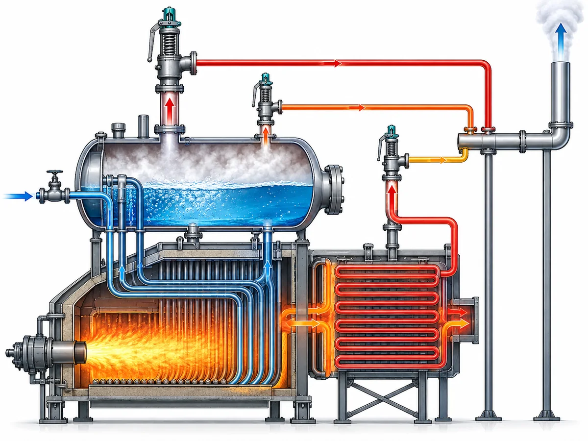
A drum-mounted valve and a valve protecting a superheater, for example, can have different pressure or capacity responsibilities under the applicable boiler rules. Some regulated boiler frameworks explicitly treat the drum and superheater separately while still relating their capacities to an overall boiler generating-capacity requirement.
The exact allocation rule is not universal, so this article does not assign a generic drum/superheater percentage. Instead, the engineer should ask two questions:
- What total relieving duty must the complete boiler protection arrangement satisfy?
- Does the governing code impose a separate local protection or capacity requirement at this valve’s installed location?
Both questions matter.
A total capacity sum may appear adequate while a specific protected section is inadequately covered. Conversely, a valve that provides essential local protection may be creditable toward the total requirement only under defined conditions.
A representative review scenario
Consider a boiler with two safety valves on the main pressure-containing section and another valve associated with a superheater.
The wrong review method is:
Add all three catalog capacities and compare the result with one boiler capacity number.
The more defensible review is:
- establish the required boiler relieving duty;
- identify which section each valve protects;
- verify the permitted setting relationship for those locations;
- identify the documented capacity basis for each valve;
- determine whether the governing rules allow each capacity to contribute to the overall requirement;
- verify any location-specific minimum or separate protection responsibility;
- then assess the combined schedule.
No numerical values are needed to understand the logic. The purpose of the scenario is to show why location is an engineering variable in capacity allocation, not merely a line in an equipment list.
It also explains why changing the location of a valve—or replacing a valve at one location with a superficially similar device—can require more than checking the flange size and set pressure.
Verify the Final Arrangement With a Valve-by-Valve Schedule
The final review should make the evidence visible valve by valve.
A useful schedule does more than list tags, sizes, and set pressures. It should allow an engineer, inspector, or supplier to trace how each valve contributes to the protection basis and where a conclusion still depends on missing project data.
A practical structure is:
| Review field | O que registrar |
|---|---|
| Valve ID | Unique tag or existing-valve identifier |
| Protected location | Drum, superheater, or other clearly defined protected section |
| Governing pressure basis | MAWP or other applicable approved basis |
| Pressão de ajuste | Proposed or existing marked setting |
| Required / allocated duty | Portion of the governing duty being checked against this valve, where the design uses an allocation |
| Capacity source | Certified capacity listing, manufacturer documentation, approved calculation, or other applicable basis |
| Capacity conditions | Relevant set pressure, relieving-pressure basis, steam condition, and design identity |
| Credited capacity | Capacity actually accepted for the schedule—not simply a catalog maximum |
| Local protection requirement | Any separate requirement associated with the installed location |
| Code / project basis | Standard, jurisdiction, project specification, or design reference |
| Supporting record | Datasheet, certification record, nameplate information, test/calibration record, or calculation reference |
| Status | Verified / conditional / confirmation required |
The value of this table is not administrative neatness. It forces the reviewer to distinguish three states:
- Proven. The capacity or pressure setting has an applicable, traceable basis.
- Conditional. The engineering relationship is understood, but final credit depends on a code edition, project rule, operating condition, or product document that still needs confirmation.
- Unresolved. The schedule contains a nominal value, but the evidence needed to rely on it has not been identified.
That distinction is more useful than a table in which every field is filled but the source and applicability of the numbers are unclear.
Recheck the whole relationship after a meaningful change
A boiler safety-valve schedule should not be treated as permanently valid simply because the valves remain physically installed.
If the required steam-generating duty is increased, the required relieving capacity can change. If one valve is replaced, its design identity or documented capacity basis can change. If a set pressure changes, the pressure/capacity relationship may need to be reconfirmed. If a valve moves to another protected location, location-specific credit can change.
The precise regulatory consequence of each modification depends on the governing jurisdiction and project requirements. But from an engineering-review standpoint, any change that alters a basis on which the existing schedule credits protection should trigger a check of that basis.
For a replacement valve, do not reduce the comparison to “same connection and same set pressure.” A defensible review may also need to compare:
- valve design or certified design identity;
- set-pressure range;
- documented steam capacity;
- applicable capacity/certification basis;
- flow-area or orifice identity where relevant;
- protected location;
- installation and back-pressure conditions where they affect applicability;
- code, project, and documentation requirements.
Matching only one or two nominal fields is identification evidence—not proof of full interchangeability.
From a Staged Valve List to a Defensible Protection Schedule
Set-pressure staging and capacity allocation should end in one coordinated engineering record.
The pressure side of that record answers: Are the valve settings permitted for this boiler and pressure basis?
The capacity side answers: Does each credited valve capacity have an applicable technical basis, and does the permitted combination satisfy the required relieving duty?
The location check answers: Is the capacity available where the governing protection requirement needs it?
The documentation check answers: Can each important value be traced to the code, calculation, certification record, manufacturer document, or test record that actually supports it?
When those questions are answered together, a multi-valve schedule becomes more than a list of set points and capacities. It becomes a reviewable protection argument.
If any of those bases are still unknown, they should remain visible as confirmation items rather than being replaced by a generic percentage or assumed catalog value.
Prepare the data before requesting an engineering review
For a project-specific review, provide the boiler type and protected sections, applicable code or jurisdiction if known, MAWP or other governing pressure basis, normal operating pressure, required steam-relieving duty or calculation basis, each valve location and set pressure, and the documentation supporting each valve’s capacity.
For an existing installation or replacement, also provide the available valve nameplate, datasheet, certification/capacity records, and information about any boiler-duty or configuration change.
The objective is not to choose a valve from the article alone. It is to give the responsible engineer and valve supplier enough information to determine whether the proposed settings and capacities form one coherent, defensible protection arrangement.