Entenda quando um líquido bloqueado cria um cenário de alívio por expansão térmica, o que determina a capacidade e a pressão de ajuste, e quais dados verificar antes da seleção da válvula.

Uma linha de líquido bloqueada pode se tornar um problema de sobrepressão quando o líquido fica retido dentro de um limite de pressão definido e sua temperatura pode subir sem espaço suficiente ou outro caminho adequado para acomodar a expansão. A primeira questão de engenharia, portanto, não é “Qual válvula de alívio para expansão térmica devo comprar?” É “Esta seção realmente cria um cenário de alívio por expansão térmica crível?”
Uma válvula fechada, por si só, não estabelece o cenário de alívio completo. O diâmetro da tubulação não determina a capacidade de alívio requerida. O serviço normal com líquido não prova que o fluido permanece em fase única através do dispositivo de alívio. Mesmo uma válvula corretamente dimensionada ainda deve ser avaliada com sua rota de descarga e a contrapressão esperada.
Definir o limite bloqueado → confirmar o cenário de expansão térmica → estabelecer a carga de alívio requerida → definir a base de pressão → verificar o estado do fluido em alívio → avaliar o sistema de saída → avaliar a válvula candidata e as evidências para a RFQ.
A orientação do HSE do Reino Unido para tubulação de processo reconhece que o líquido pode ficar retido entre válvulas fechadas e que variações de temperatura podem então causar expansão térmica e perda de contenção. Ela também enquadra o alívio de pressão em torno das condições reais de operação e isolamento, e não apenas da presença de uma válvula. Orientação do HSE para tubulações.
Para um contexto mais amplo de sobrepressão em tubulações, consulte o guia de aplicação de alívio em tubulações da ZOBAI. Essa página aborda vários cenários de sobrepressão em tubulações; este artigo mantém o foco na expansão térmica de líquido bloqueado.
Quando uma linha de líquido bloqueada se torna um caso de sobrepressão por expansão térmica?
Um caso de expansão térmica começa com um fronteira de pressão real com líquido retido,
não simplesmente com baixa vazão ou uma válvula fechada.
-
Defina a fronteira de isolamento.
Identifique as válvulas, interfaces de equipamentos ou outros pontos de isolamento que podem reter o líquido. -
Determine o que está retido.
Estabeleça se a seção pode ficar completamente cheia de líquido ou de outra forma suficientemente confinada
para que a expansão térmica seja relevante. -
Identifique um aumento de temperatura plausível.
Considere condições operacionais, de parada, de espera ou ambientais relevantes que possam aquecer
o líquido retido. -
Compare o cenário com a fronteira de pressão protegida.
Determine se a condição resultante pode desafiar a base de pressão aplicável para
a tubulação ou o equipamento.
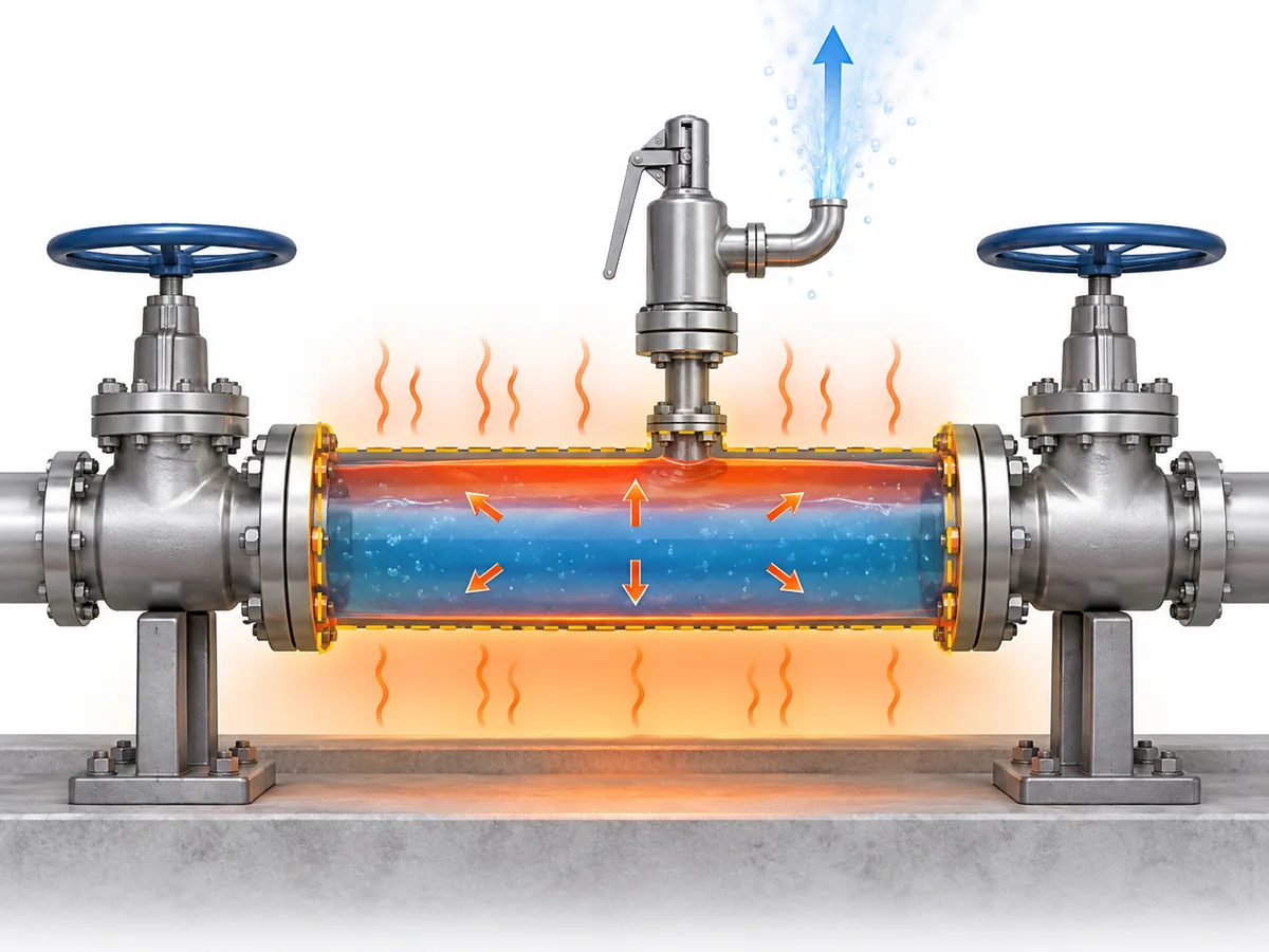
Os líquidos são muito menos compressíveis que os gases. Quando um volume isolado está substancialmente
preenchido com líquido, o volume adicional de líquido gerado pelo aquecimento pode, portanto, se traduzir em
um aumento acentuado de pressão, a menos que o sistema tenha uma forma adequada de acomodar ou aliviar essa pressão.
A entrada de calor é específica de cada instalação. Dependendo do sistema, as fontes relevantes podem incluir
aquecimento ambiente ou solar, traçagem térmica, uma área ao redor aquecida ou equipamentos de processo
adjacentes. A presença de uma dessas fontes não a torna automaticamente o caso determinante;
a condição plausível deve ser estabelecida para a instalação real.
Bloqueado não significa apenas “sem fluxo”.”
Significa que o sistema pode criar um limite de pressão de líquido confinado em condições
nas quais a expansão térmica pode desafiar esse limite.
Essa é a condição a ser estabelecida antes do dimensionamento ou da seleção de um dispositivo de alívio.
Toda seção de líquido bloqueada precisa de uma válvula de alívio térmico dedicada?
Não automaticamente.
Identificar um cenário de expansão térmica confiável estabelece que o risco de sobrepressão
exige uma resposta de engenharia adequada. Isso não prova, apenas com base no cenário, que
um arranjo específico de válvula de alívio térmico dedicada seja a única solução aceitável.
| Questão de engenharia | O que foi realmente estabelecido? |
|---|---|
| O líquido pode ficar retido e aquecer? | Existe um potencial cenário de expansão térmica. |
| Essa condição pode desafiar o limite de pressão protegido? | A proteção contra sobrepressão deve ser avaliada. |
| A solução deve ser uma válvula de alívio térmico dedicada? | Isso depende da estratégia de proteção aceita e da base do projeto. |
| Uma válvula específica é adequada? | Isso exige um regime de operação definido e evidências específicas do produto. |
Dependendo do sistema e da base de engenharia aplicável, a proteção pode envolver uma
pressure-relief device or another engineered arrangement that prevents unacceptable
pressure from developing. A solution accepted for one service or jurisdiction should
not be generalized to every process line.
API Standard 521 is a system-level pressure-relief and depressuring reference for petroleum,
petrochemical, LNG and related facilities. Its scope supports evaluating the relief scenario
and system before treating a product name as the design decision.
API Standard 521 information.
The terminology can also mislead procurement. Válvula de alívio hidrostático
is used in some industries for devices protecting piping where liquid can be trapped
between shut-off valves. That practical terminology overlap does not make
“hydrostatic relief valve” and “thermal relief valve” universally interchangeable across
every fluid, code or industry.
Scenario confirmed → protection strategy defined → applicable project/code basis checked
→ device selected and verified.
For broader standards context, see
ZOBAI’s API 521 pressure-relief systems guide
.
What Determines the Required Thermal Relief Rate and Valve Capacity?
A thermal expansion relief valve should be selected from the
required relieving duty, not from pipe diameter or a habitual
“small thermal valve” size.
For a liquid-filled thermal-expansion case, the relief requirement depends on the thermal
condition and on fluid properties that determine how the liquid responds as temperature
changes. Once the required relieving flow is established, actual valve sizing also depends
on the applicable relieving pressure, temperature, outlet/back-pressure condition and
fluid state.
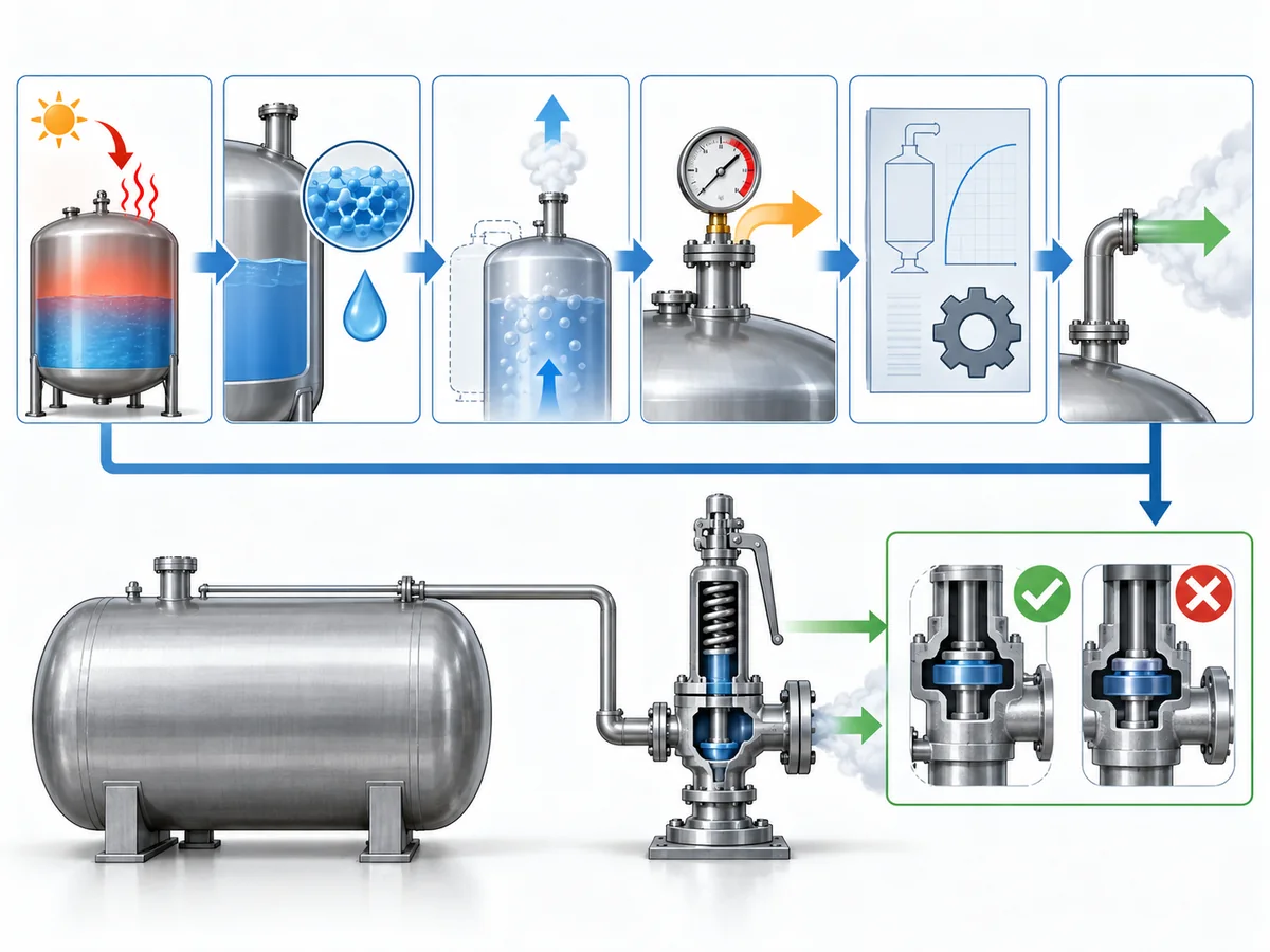
Credible thermal condition → applicable fluid properties → required relieving rate
→ relieving pressure and outlet conditions → applicable sizing method
→ required flow area/capacity → candidate valve capacity verification.
Two shortcuts are worth rejecting. O tamanho da conexão não é capacidade:
a valve may fit the line mechanically while still lacking the capacity required for the
relief case. And “thermal relief flow is often relatively small” is not a sizing
method: even a modest duty has to be established before a candidate valve can
be accepted.
API 520 Part I is specifically concerned with pressure-relieving-device sizing and
selection within its scope.
API 520 Part I information.
For the detailed general sizing workflow rather than repeating it here, see
ZOBAI’s safety valve sizing and certified relieving capacity guide
.
The practical inputs for this thermal-expansion case include:
- the protected section and relevant trapped volume;
- the credible thermal condition or heat input;
- fluid identity and the physical properties required by the applicable calculation;
- pressão e temperatura de alívio;
- the required relieving rate;
- expected back pressure; and
- the fluid-state assumption used by the sizing method.
Only after the required duty has been established should the selected valve’s documented
capacity be compared against it.
Thermal relief is duty-sized, not simply small-sized.
How Should the Set-Pressure Basis Be Established?
Set pressure should be derived from the pressure boundary being protected,
not copied from normal operating pressure or selected from a generic percentage rule.
That separation is consistent with recognized relief-device specification practice:
operating pressure, set pressure, relieving/design temperatures, allowable overpressure,
back pressure and required capacity are treated as distinct inputs rather than
interchangeable values.
Baker Hughes pressure-relief valve specification guidance
.
| Termo de pressão | Role in the thermal-relief decision |
|---|---|
| Pressão de operação | The pressure the system normally experiences. |
| Protected design / allowable pressure basis | The applicable pressure boundary for the piping or equipment being protected. |
| Pressão de ajuste | The specified pressure associated with the relief device beginning its defined opening action. |
| Pressão de alívio | The pressure condition used for relief sizing or capacity assessment. |
| Contrapressão | Pressure acting on or downstream of the valve outlet. |
Those values are related, but they are not interchangeable. Identify which piping and
components lie inside the blocked-in boundary, then establish the governing pressure basis
under the applicable design code, equipment rules and project specification before
assigning the valve set pressure.
Scope discipline matters here. A pressure rule written for a vessel should not automatically
be transplanted into generic process piping, and a regulation written specifically for LPG,
ammonia or another service should not be generalized to unrelated fluids or jurisdictions.
This article therefore does not create a universal rule such as
“set the thermal relief valve at a fixed percentage above operating pressure.”
Where a numerical relationship is prescribed, it belongs to the applicable equipment,
code, project and jurisdictional basis.
For an RFQ, set pressure should be treated as the result of a protected-system engineering
decision, not merely as a field to complete on a vendor datasheet.
Why the Relieving Fluid State Must Be Checked, Not Assumed
A line can be liquid-filled before the relief event without remaining a simple
single-phase liquid system throughout the complete relieving path.
Relief-valve engineering guidance distinguishes straightforward liquid sizing from cases
in which subcooled liquid can flash as pressure falls through the valve. That makes the
relieving-state check a real sizing boundary rather than a semantic detail.
LESER engineering guidance.
As pressure changes through the valve and downstream piping, the relationship between fluid
pressure and temperature can change. Under some conditions, the liquid remains adequately
subcooled and a liquid-sizing basis remains appropriate. Under others, flashing or a more
complex phase condition may need to be considered.
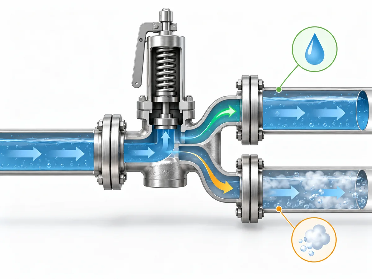
At the relevant relieving pressure and temperature—and as pressure falls through the
valve and outlet system—does the fluid remain in the phase assumed by the sizing method?
If the assumed phase remains valid, the case can continue under the appropriate liquid-sizing
methodology. If meaningful phase change occurs, the required inputs and sizing treatment can
change. That does not mean every thermal-expansion case is two-phase; it means the phase
assumption should be verified rather than inherited from the normal operating description.
A procurement description such as “liquid service, thermal relief”
therefore does not by itself prove the relieving-state assumption required for final sizing.
This article treats initial phase e relieving phase
as related but separate engineering inputs.
Why Discharge Routing and Back Pressure Are Part of the Relief Decision
A correctly selected valve is not enough if the installed relief path cannot perform
under the defined scenario.
Protected section → valve inlet → relief device → outlet piping → disposal or recovery destination.
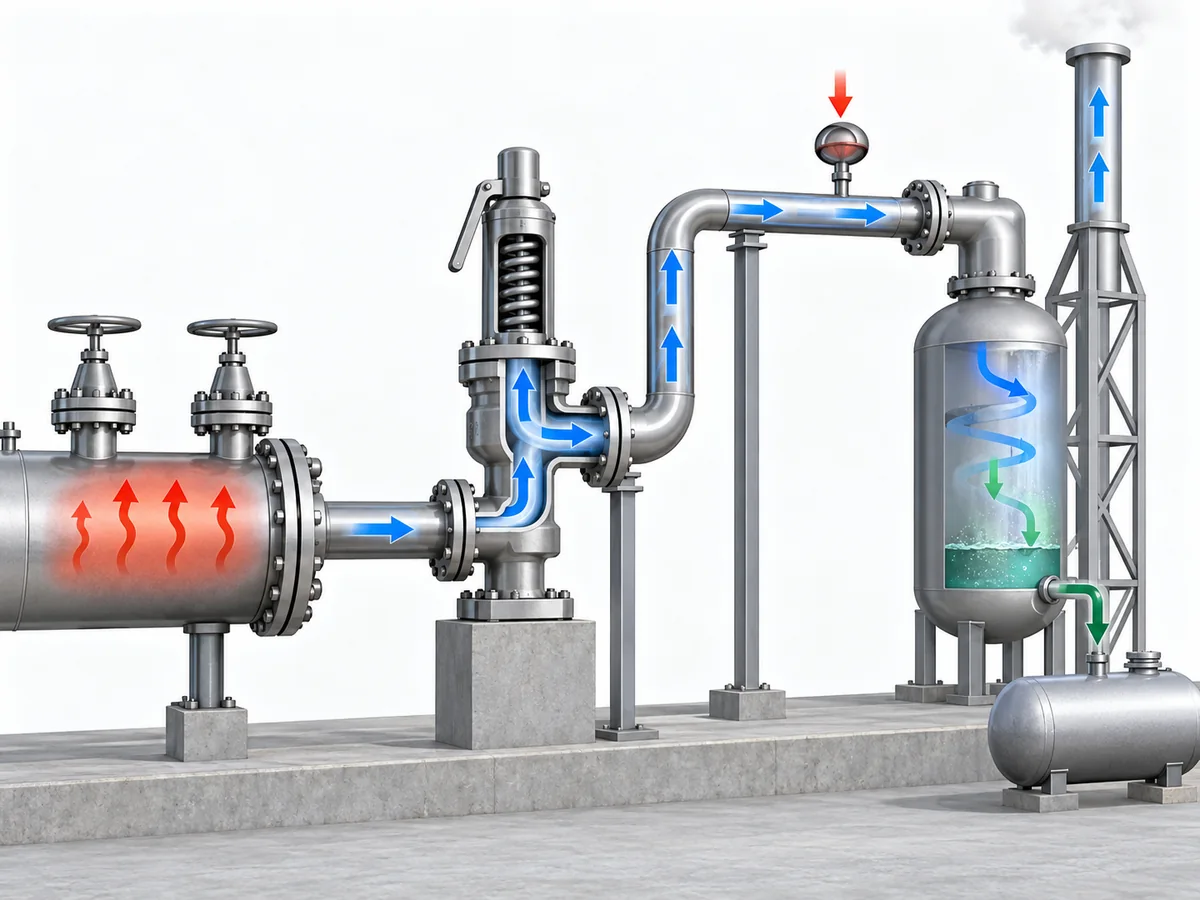
The review should establish where the relieved liquid will go, whether that route remains
available during the relief case, and what pressure the downstream system will impose on
the valve.
Back pressure can influence relief-valve behavior and available capacity, depending on the
valve design and system. Emerson’s pressure-relief-valve engineering handbook treats back
pressure as a factor that can affect opening or reseating behavior, stability and capacity,
so it belongs in candidate verification rather than being left as a post-purchase piping detail.
Emerson Pressure Relief Valve Engineering Handbook
.
For a deeper treatment of that interface, see
ZOBAI’s back-pressure and bellows engineering guide
.
The destination itself is service-dependent. A small expected thermal-relief rate does
not prove that unrestricted atmospheric discharge is acceptable. Conversely, a closed
return, drain or recovery system is not automatically suitable if it imposes unacceptable
back pressure or can be isolated when relief is required.
ISO 23251 provides an international pressure-relief-system framework for petroleum,
petrochemical and natural-gas industries. Its current 2019 edition explicitly supplements
API 521 6th Edition, so project teams should confirm the adopted standard set rather than
silently treating different editions as textually equivalent.
ISO 23251 information.
Where can the relieved fluid go without compromising either safe disposal or the valve’s
ability to perform its relief function?
Detailed flare design, closed-header hydraulics and valve-architecture thresholds belong
to separate engineering work. This article only needs to establish that the outlet system
forms part of the relief decision.
What Information Belongs in a Thermal-Relief RFQ or Engineering Review?
A technically useful RFQ should describe the protected system and relief duty,
not simply request a valve by nominal size.
Separate the process inputs from the supplier verification:
| Buyer / engineer should define or assign | Supplier / candidate should confirm |
|---|---|
| Protected piping or equipment boundary | Exact valve configuration offered |
| Fluid and relevant composition | Wetted-material, seat and seal suitability |
| Normal fluid state | Pressure-temperature suitability |
| Pressão e temperatura de operação | Available set-pressure capability |
| Governing protected-pressure basis | Documented capacity for the specified duty |
| Credible thermal condition or heat source | Selected flow area or valve size |
| Required relieving rate, or responsibility for determining it | Effect of specified back pressure on the candidate |
| Relieving-phase assumption | Connection and pressure-class suitability |
| Contrapressão esperada | Applicable inspection or test documentation |
| Relief destination | Requested conformity documentation, where applicable |
| Applicable project code or specification | Deviations, limitations and unresolved points |
Required relieving capacity is not the same as connection size.
One is a process-protection requirement; the other is primarily an installation characteristic.
Required capacity is also not the same as compliance evidence.
Capacity documentation addresses the flow-performance question under the applicable basis.
Material certificates, inspection records or other project-required conformity evidence
answer different procurement questions.
A supplier should not have to guess the relief scenario. If the protected pressure basis,
thermal condition, required relieving rate, fluid state or expected back pressure remains
undefined, those gaps should be resolved before a proposed valve is treated as an approved
candidate.
Can the proposed valve be traced back to a defined thermal-expansion duty, protected
pressure boundary, relieving state and outlet condition—and does the supplier evidence
address each of those requirements?
If not, the candidate is not ready for approval merely because a catalogue uses the words
alívio térmico ou hydrostatic relief.