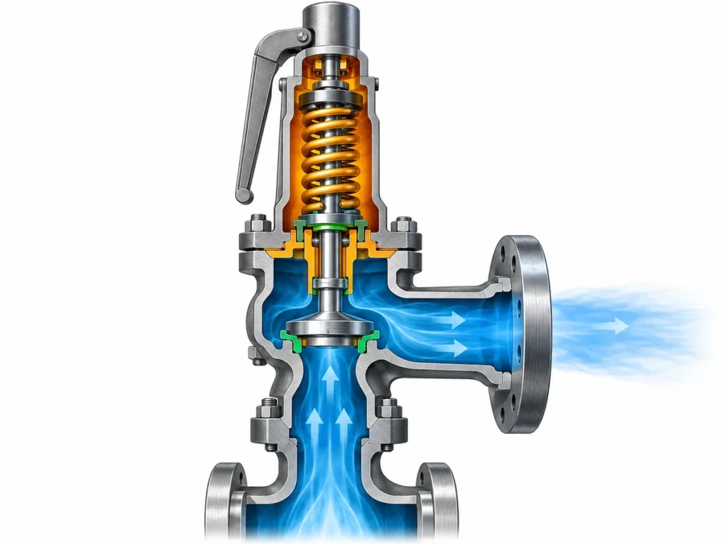
Découvrez quand les soupapes de sûreté à enveloppe chauffante conviennent au service du soufre, ce que l'enveloppe peut et ne peut pas résoudre, et quelles vérifications de dimensionnement, de contre-pression, de matériaux et de demande de prix restent nécessaires.

Les soupapes de sûreté à enveloppe chauffante pour le service du soufre conviennent lorsque la perte de température au niveau de la soupape pourrait permettre au fluide de procédé de se solidifier ou de devenir difficile à déplacer dans le circuit de décharge. L'enveloppe est un dispositif de régulation thermique autour de la zone de la soupape qu'elle chauffe effectivement. Elle ne remplace pas le dimensionnement de la décharge, la vérification documentée ou certifiée de la capacité, les contrôles de perte de charge à l'entrée et de contre-pression, l'examen des matériaux, ni la gestion thermique des tuyauteries amont et aval.
Cette distinction est essentielle pour spécifier correctement la soupape. Un système de décharge pour soufre peut être thermiquement adéquat au niveau du corps de soupape tout en restant vulnérable au niveau d'une branche d'entrée ou d'une conduite de décharge plus froide. Inversement, le maintien en température ne prouve pas que la soupape sélectionnée dispose d'une capacité de décharge suffisante pour le scénario déterminant. La tâche d'ingénierie consiste donc à vérifier trois questions distinctes : le circuit de décharge reste-t-il thermiquement utilisable, la soupape peut-elle assurer le service de décharge requis, et la construction retenue est-elle compatible avec le service réel du soufre.
Soupapes de sûreté à enveloppe chauffante pour le service du soufre : pourquoi la sélection change
Le service du soufre introduit une variable moins importante dans de nombreuses applications ordinaires de décharge de gaz ou de liquide : l'état physique du fluide de procédé peut évoluer sensiblement avec la température.
Le soufre élémentaire est couramment traité à l'état fondu au-dessus de sa zone de solidification. Si une section stagnante du circuit de décharge perd suffisamment de chaleur, le soufre peut se solidifier et créer une restriction. Cette possibilité compte même lorsque la soupape de sûreté elle-même présente la pression de tarage et le diamètre nominal de raccordement corrects. Un dispositif de décharge ne peut pas protéger l'équipement comme prévu si le circuit nécessaire pour atteindre ou quitter la soupape est matériellement restreint.
La question d'ingénierie n'est pas simplement de savoir si le procédé est appelé “ service du soufre fondu ”. L'ingénieur doit comprendre la composition et l'état réels du soufre, les températures normales et de décharge, la durée pendant laquelle des sections peuvent rester stagnantes, et ce qui se produit au niveau de la température en veille et après un événement de décharge.
La régulation de température ne doit pas non plus se résumer à “ plus chaud est toujours mieux ”. Le comportement du soufre dépend de la température, et sa viscosité peut augmenter sensiblement à des températures plus élevées dans certaines plages. L'objectif de conception utile est donc de maintenir la plage de fonctionnement définie par le projet, not to maximize heating without limit.
This is why a jacketed configuration should be selected from the service condition outward. First define where cooling or solidification could impair the relief path. Then determine which parts of that path need temperature control and whether a jacketed valve is one appropriate part of that strategy.
What the Jacket Can—and Cannot—Do
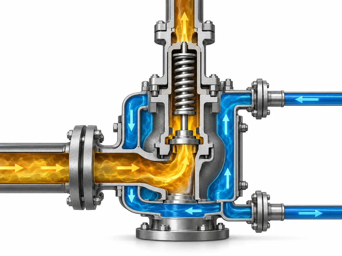
A jacketed safety valve adds a separate heating space around part of the valve. A heating medium such as steam can circulate through that jacket and transfer heat toward the process-wetted valve region.
The process medium and the jacket medium are two different flow systems. Sulfur passes through the safety-valve flow path. The heating medium circulates through the surrounding jacket or body interlayer. Their functions should not be confused: the process side provides the pressure-relief path, while the jacket side helps control temperature around the section it heats.
That physical boundary is important. The jacket can reduce local cooling risk at the valve body, but it cannot directly heat piping or equipment outside its coverage unless those parts have their own thermal-control provisions.
| Question d'ingénierie | What the jacket may contribute | What still requires separate verification |
|---|---|---|
| Keep the valve region warm | Provides heat around the jacketed portion of the valve | Required sulfur temperature envelope and actual heat-transfer performance |
| Protect the inlet branch from solidification | Only where the inlet region is actually within the heated boundary | Nozzle, inlet piping, tracing, insulation or other thermal-control arrangement |
| Keep the discharge path open | Only within any specifically heated outlet region | Downstream piping, header, drainability and post-relief cooling |
| Provide enough relieving capacity | No direct proof | Governing relief load, selected flow area and documented/certified capacity |
| Solve back-pressure problems | Non | Superimposed and built-up back pressure plus discharge-system behavior |
| Prove sulfur compatibility | Non | Body, trim, bellows, seat, seal, gasket and project material requirements |
ZOBAI’s current catalog provides a useful product-level example of this distinction. The ZBNJ Series Safety Valve with Jacket is shown with circulating steam used for thermal insulation through a body interlayer, and the series documentation separates individual variants rather than presenting one universal rating for every jacketed valve. Exact pressure, temperature, material and dimensional limits therefore have to be checked against the selected model rather than inferred from the family name. For broader product-family information, review ZOBAI’s Soupapes de sûreté à enveloppe chauffante.
A jacket should consequently be specified because a defined part of the relief path needs thermal control—not because the word “sulfur” automatically calls for a jacketed valve.
Treat the Entire Relief Path as a Thermal Boundary
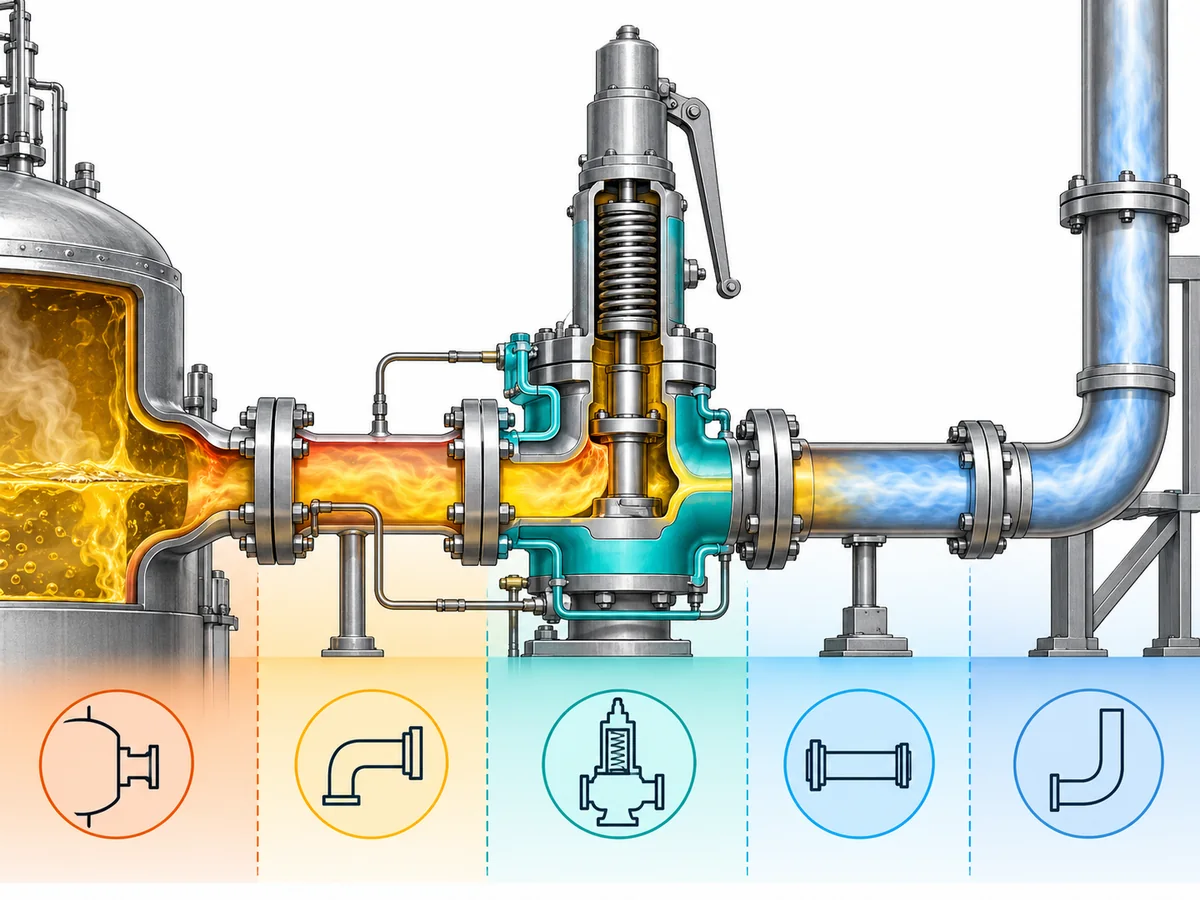
Once the valve body has been considered, the next question is where the process medium travels before and after the valve opens.
For a typical relief arrangement, that can include the protected equipment nozzle, inlet piping, valve inlet and body, outlet connection, discharge piping and possibly a common header or disposal system. If sulfur condition depends strongly on temperature, these elements form a thermal chain. The temperature of one well-heated component does not prove that every other segment will remain in an acceptable condition.
Consider a representative engineering scenario. The vessel nozzle and valve body are maintained at the required temperature, and the valve has a heating jacket. The outlet, however, runs into a longer discharge line that is thermally managed differently. After a relief event, sulfur entering that colder section can cool independently of the valve body. The jacket therefore cannot be treated as evidence that the entire discharge route remains suitable.
The opposite condition can also occur upstream. A jacketed valve may remain warm while a stagnant inlet branch or nozzle loses temperature. In that case, the restriction risk exists before the flow reaches the valve.
The practical review should therefore map the thermal condition of the relief path rather than checking only the product description:
- Where can sulfur remain stagnant during normal operation?
- Which portions are heated by the valve jacket?
- Which portions rely on tracing, insulation, another jacket or process heat?
- What happens to temperature during startup, shutdown and standby?
- What happens downstream after a relief event?
- Can condensate, deposits or retained process material create an additional local restriction?
- Can the heating arrangement be inspected, drained and maintained?
These questions do not dictate one universal tracing or insulation design. They define what the project engineer needs to verify. For the broader piping and installation considerations that sit outside this sulfur-specific article, see the guide d'installation des soupapes de sûreté.
A useful selection rule: the thermal adequacy of a sulfur relief system is governed by the complete path that must remain available, not by the temperature of the jacketed valve body alone.
Heating Strategy Does Not Replace Relief Sizing, Capacity, or Back-Pressure Checks
Thermal control and pressure-relief performance solve different engineering problems.
The thermal system helps keep sulfur in the required physical condition. Relief sizing determines whether enough flow can pass through the selected device under the governing overpressure scenario. Both must be satisfactory.
The first pressure-relief question is therefore still the governing scenario. The engineer needs the required relieving load based on the protected equipment and credible relief case. From there, the selected valve and flow area must be checked against the applicable capacity basis under the relevant relieving conditions. ZOBAI’s le dimensionnement des soupapes de sûreté et la capacité certifiée guide covers that deeper sizing workflow.
A nominal inlet size cannot be used as a shortcut for this verification. Likewise:
- set pressure is not relieving capacity;
- connection size is not relieving capacity;
- a jacketed body does not establish certified or documented capacity;
- thermal adequacy does not establish acceptable inlet pressure loss;
- thermal adequacy does not establish acceptable back pressure.
Back pressure deserves particular attention because the discharge system can interact with valve performance. Sulfur-service thermal management may also add practical constraints to the outlet arrangement, but those constraints do not remove the need to evaluate superimposed and built-up back pressure using the applicable valve configuration, manufacturer data and project design basis. The dedicated back pressure and balanced bellows engineering guide addresses that subject in more depth.
A balanced-bellows configuration, where selected, similarly should not be described as an automatic solution to every back-pressure condition. The actual allowable conditions remain configuration- and manufacturer-dependent.
This separation aligns with the way major pressure-relief references divide responsibilities. Dimensionnement des soupapes de sûreté selon API 520 traite du dimensionnement et de la sélection, tandis que Systèmes de décharge de pression selon API 521 addresses the wider pressure-relieving and depressuring system. ASME BPVC Section XIII addresses overpressure-protection requirements including pressure-relief-device performance and capacity-related responsibilities. These documents can guide engineering review, but their names alone do not prove that a particular ZOBAI valve is certified for a specific project.
The practical result is a two-track verification:
Thermal track: Will sulfur remain in the project-required condition throughout the necessary relief path?
Pressure-relief track: Can the selected device and discharge arrangement provide the required protection under the governing relief case?
A valid design needs satisfactory answers to both.
Materials, Configuration, Installation, and Maintenance Still Control Suitability
Even after the need for a jacket has been established, “jacketed” is not a complete valve specification.
Material compatibility depends on the actual service
Body material is only one part of the wetted construction. Depending on the selected valve, the nozzle, disc, guide, spindle, bellows, seat, seal and gasket may introduce different material or temperature limitations.
Le mot sulfur is not enough to select those materials. Actual process composition, contaminants, water or H₂S where relevant, operating and relieving temperature, cleaning method and project material requirements can change the decision.
For that reason, generic statements such as “stainless steel is required for sulfur” or “carbon steel is suitable for sulfur” are too broad without a defined service basis. The selected model should be reviewed component by component against the real process and project specification.
The heating circuit has its own design limits
The jacket is also a pressure-and-temperature boundary in its own right. The RFQ should therefore define the heating medium and its conditions rather than simply requesting “steam jacketed.”
Relevant questions include:
- What heating medium is available?
- What are its pressure and temperature?
- Is the utility continuous or intermittent?
- What jacket connections are required?
- How will the heating medium circulate and return?
- How will condensate or retained utility fluid be managed?
- What is the selected valve’s jacket-side allowable pressure and temperature?
- Are the jacket materials compatible with the heating utility?
ZOBAI’s catalog identifies circulating steam for thermal insulation in the ZBNJ body interlayer, but the exact jacket-side allowable conditions still require selected-model data. They should not be copied from another manufacturer or inferred from the process-side valve rating.
Installation can preserve—or defeat—the intended thermal strategy
A technically suitable valve can still be undermined by an installation that creates a cold or restrictive section elsewhere.
The engineering review should therefore consider the inlet arrangement, outlet and discharge route, insulation or tracing interfaces, drainage, pipe support, accessibility and maintenance requirements. Where a bellows is used, its vent arrangement must remain consistent with the selected design and manufacturer’s requirements. Heavy discharge piping should also be supported independently rather than using the safety valve as a structural support.
Maintenance matters because sulfur that has cooled or accumulated during an outage can change the startup condition of the relief path. Inspection and maintenance planning should address areas where solidified material could remain, but the article cannot prescribe a universal cleaning interval or procedure without project and manufacturer information.
The resulting selection decision is multi-variable: a valve may have the required jacket configuration yet still be unsuitable because of its materials, jacket utility limits, capacity, back-pressure condition or installation arrangement.
What to Specify Before RFQ or Engineering Review
A useful RFQ for sulfur service should describe the relief duty and thermal duty together. Sending only the nominal valve size, set pressure and the phrase “for sulfur” leaves too many engineering variables unresolved.
The following information provides a practical starting point.
Process and relief basis
- Protected equipment.
- Governing relief scenario.
- Normal operating pressure.
- Design pressure or MAWP, as applicable to the project.
- Required set pressure.
- La capacité de décharge requise et la base de calcul.
- Relieving pressure and temperature, where established.
- Sulfur composition, phase and relevant contaminants.
- Normal, startup, shutdown and standby temperature conditions where they affect solidification risk.
Relief-path and back-pressure information
- Inlet connection and inlet-piping arrangement.
- Outlet connection.
- Expected superimposed back pressure.
- Information needed to evaluate built-up back pressure.
- Discharge destination or header arrangement.
- Thermal-control method for the equipment nozzle, inlet branch and downstream piping.
- Drainage or retained-liquid concerns where applicable.
Jacket and heating utility
- Heating-medium type.
- Available heating-medium pressure.
- Available heating-medium temperature.
- Required jacket connection arrangement.
- Utility supply and return arrangement.
- Condensate or drainage requirements.
- Whether adjacent equipment and piping are separately traced, insulated or jacketed.
Valve construction and project requirements
- Required body material.
- Trim, bellows, seat, seal and gasket requirements where specified.
- Applicable project code or standard.
- Certification and documentation requirements.
- Inspection or witness requirements.
- Existing datasheet, nameplate or drawing when the work involves replacement.
This information allows the manufacturer and project engineer to test the relevant decisions separately: thermal adequacy, relieving capacity, back-pressure compatibility, material suitability and jacket-side limits.
Safety and code boundary: This article provides an engineering framework for evaluating jacketed safety valves in sulfur service. It does not replace the governing relief calculation, manufacturer capacity data, selected-model pressure/temperature limits, applicable code review, material-compatibility review, or project/jurisdiction acceptance. Those items must be confirmed for the actual installation.
If you are preparing a sulfur-service valve specification, send the actual process conditions, governing relief case, required relieving capacity, piping/back-pressure information, heating-medium conditions and project requirements for an engineering review. The useful question is not simply, “Do you have a jacketed safety valve?” It is, “Does this selected configuration remain thermally available and provide the required pressure protection under my actual service conditions?”
Need a project-specific review? Provide the actual sulfur-service conditions, relief case, capacity basis, back-pressure information, heating-medium conditions, and applicable project requirements.