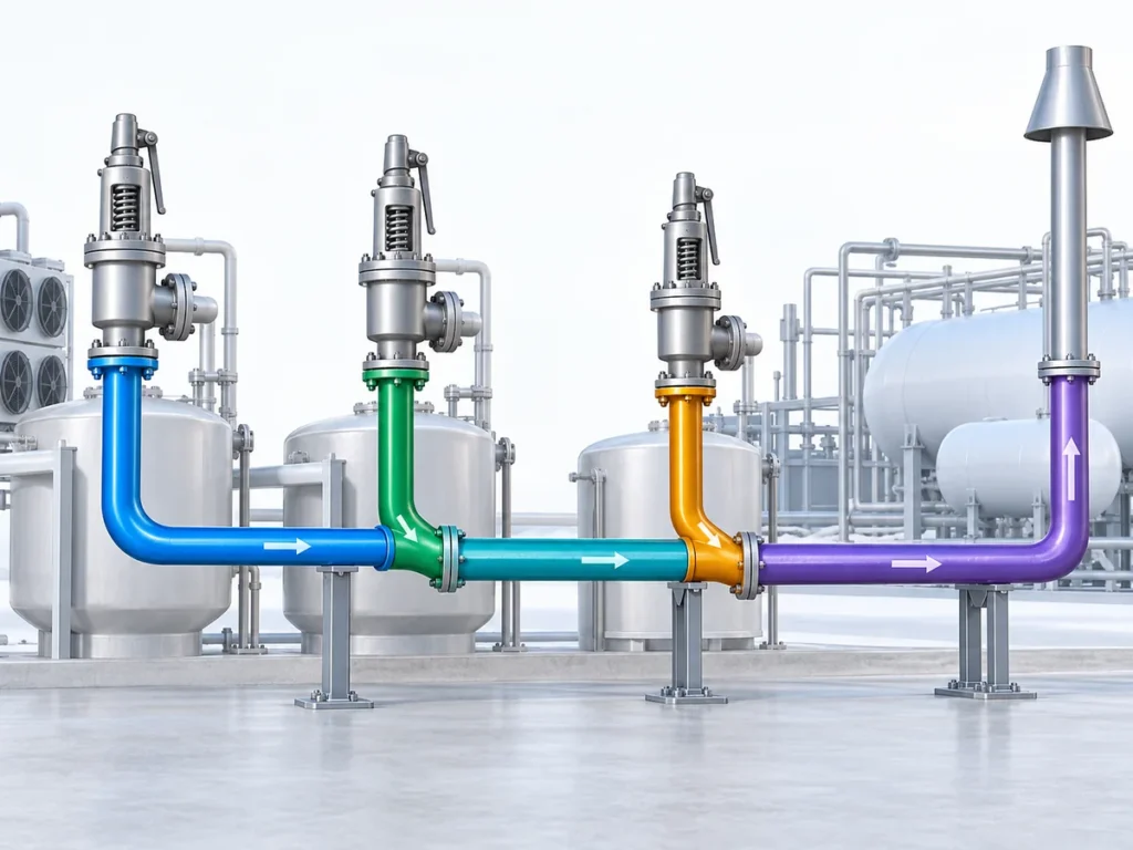
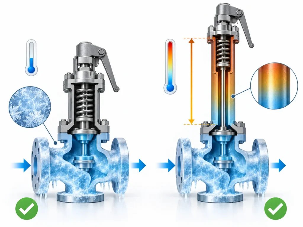
Learn where frost and ice can affect an LNG safety valve discharge, how blockage differs from back pressure, and what engineers should verify before acceptance.

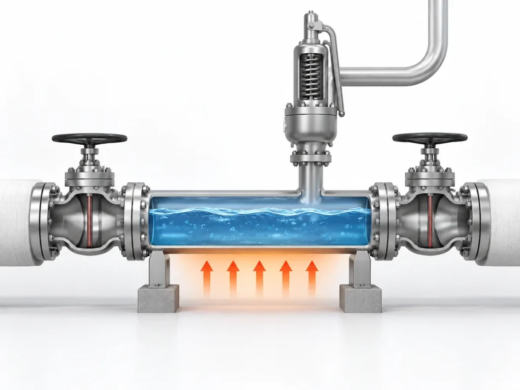
Ice or frost around an LNG safety valve discharge is a warning to investigate, not a diagnosis by itself. A white deposit on cold piping does not establish that the relief path is blocked, that the LNG itself has frozen, or that back pressure is the problem.
The engineering task is more specific: identify what is freezing, where the deposit is forming, whether a required valve or discharge function is affected, and what the actual relieving condition is. Only then can an icing concern be separated from ordinary cryogenic surface frosting, downstream restriction, back pressure, or an unresolved valve-application issue.
This page focuses on that discharge-side review. It does not replace relief sizing, LNG phase calculations, vent or flare-system design, or approval by the responsible project engineer. For broader application and valve-selection context, see the LNG safety valve applications guide.
What Actually Causes Ice or Frost Around an LNG Safety Valve Discharge?
Das Wort ice is easy to overuse in cryogenic service.
Several different physical conditions can produce something that looks like
icing, and they should not be treated as interchangeable.
General
cryogenic safety guidance from
Lawrence Berkeley National Laboratory
shows one important mechanism: very cold surfaces can cause moisture from
surrounding air to condense and freeze. In other cryogenic systems,
accumulated ice can become functionally important if it enters a vent
passage or interferes with valve movement. That guidance is useful for the
physical mechanism, but its scope is not LNG-specific, so it should not be
treated as LNG application evidence.
LNG-specific and liquefied-gas rules independently confirm that icing can
matter to pressure-relief equipment.
Bureau Veritas gas-fuelled-ship
rules
require PRVs on low-temperature fuel tanks to be arranged so ice formation
does not make them inoperative and require ambient-temperature ice effects
to be considered in PRV construction and arrangement. That is strong
evidence that PRV icing is a real design concern, but it remains a marine
liquefied-gas rule, not a universal land-based LNG requirement.
A separate point matters just as much:
visible frost is not automatically frozen LNG.
Pure methane has a well-defined triple point, but actual LNG is a
multicomponent mixture. NIST treats LNG thermodynamic behaviour with a
multicomponent equation of state rather than as pure methane alone.
Pure-methane phase data from NIST
can therefore help explain terminology, but it cannot establish the phase
condition of a project LNG mixture.
Before calling a deposit “LNG icing,” ask:
- Is atmospheric moisture freezing on an externally cooled surface?
- Is another condensable substance involved?
- Is frozen material entering a function-critical passage?
- Is there actual process evidence that the LNG mixture is approaching a solidification condition?
The answer changes what needs to be investigated. A cold external surface
and a restricted discharge passage are not the same problem.
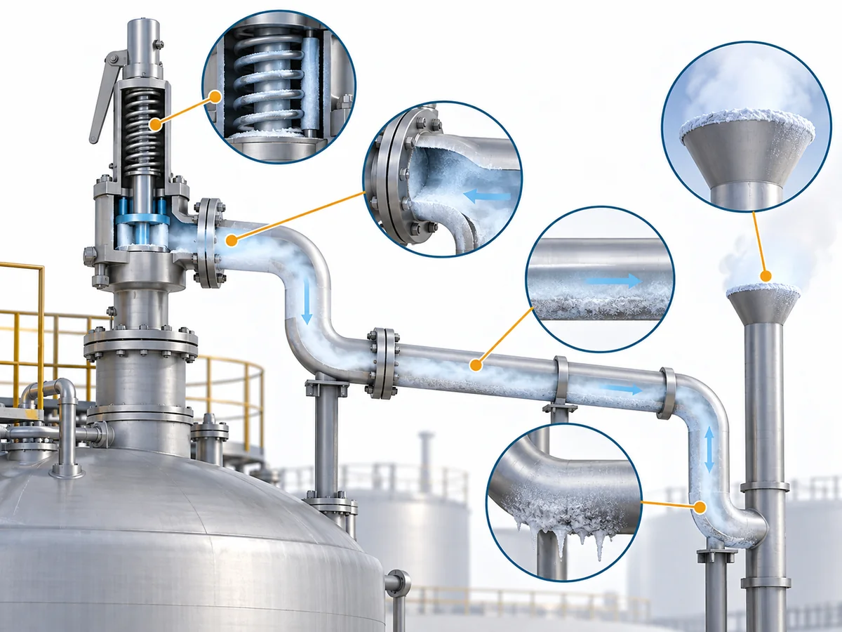
Where Can Ice Formation Matter in the LNG Relief Path?
Location determines consequence. A frosted section of external pipe may
have little relationship to the available relief flow area. Ice around a
moving component, inside an outlet passage, or at a vent termination can
be a different matter because those locations perform a function that must
remain available during a relief event.
| Standort | Why it may matter | What the review needs to establish |
|---|---|---|
| External valve or pipe surface | Frost can reflect cold surface temperature without proving internal restriction. | Whether the condition is expected and whether any required function is affected. |
| Valve operating area | Deposits may matter if they interfere with required movement. | Whether the exact valve construction exposes a function-critical mechanism. |
| Outlet or vent passage | Frozen material can matter if it reduces the effective discharge path. | Whether an internal obstruction actually exists. |
| Downstream piping | Geometry, low points or accumulated material can create additional restrictions. | Actual installed flow path and relevant accumulation mechanisms. |
| Vent termination | Ice, water, snow or foreign matter may affect outlet availability in some installations. | Whether the termination remains clear for the defined environment. |
| Pilot sensing or exhaust path | Small passages introduce different low-temperature failure modes. | Exact pilot arrangement and manufacturer evidence. |
Marine liquefied-gas rules explicitly recognize PRV icing and the need to
protect pressure-relief arrangements from becoming inoperative. These
sources establish the engineering relevance of location, but their
maritime scope must remain visible.
Pilot-operated valves deserve a separate boundary. The main valve may look
suitable for low-temperature duty while the pilot, sensing path, tubing,
seals or exhaust arrangement still need independent review. See the
guide to pilot-operated safety valves for LNG service
for that deeper decision.
The practical rule is:
find the required function first, then determine whether icing can
interfere with that function.
When Does Visible Frost Become a Functional Restriction?
Visible frost becomes a pressure-relief concern when evidence indicates
that it is affecting—or could credibly affect—a function needed for relief.
That is different from judging the system by appearance.
In its guidance for static vacuum-insulated cryogenic vessels,
EIGA DOC 224
notes that frost or ice can occur around pipes, valves, controls and
vaporisers during normal cold operation, while new or abnormal frosting
warrants separate attention. That distinction supports using frost as an
observation, not as a standalone diagnosis of either blockage or safety.
Ice at a vent passage or valve mechanism can still be significant. These
two facts mean that neither of the following shortcuts is defensible:
“There is frost, therefore the valve is blocked.”
“Frost is normal, therefore there is no problem.”
A more useful screen is to move from observation to function.
1. Locate the condition
Is the frost limited to an external surface, or is it concentrated around
a valve mechanism, outlet passage, vent termination or another
function-critical area?
2. Ask what function could be lost
Could the condition interfere with valve movement, reduce the available
discharge path, block a termination, or affect another required
pressure-relief function?
Der
Bureau Veritas liquefied-gas rules
treat prevention of PRV inoperability from ice formation as an explicit
design issue within their applicable marine scope.
3. Compare it with the operating condition
Is the frost pattern consistent with a known cold operating condition, or
is it new, persistent, asymmetric or otherwise unexplained?
4. Look for evidence beyond appearance
Relevant evidence may include inspection findings, pressure and
temperature data, downstream conditions, known vent behaviour and the
actual valve/discharge configuration.
5. Keep unresolved function-critical cases unresolved
If the available evidence cannot show that the required valve movement and
discharge path remain available, the installation should not be declared
acceptable simply because the external frost “looks normal.”
In diesem Artikel, HALTEN means an engineering-screening status
pending adequate evidence. It is not a regulatory classification.
How Do Relief State, Temperature and Flashing Conditions Change the Risk?
An LNG label does not define the relieving state.
The protected system may normally contain cold liquid, vapour, or a
mixture under one pressure and temperature, while the governing relief
event produces a different condition.
PHMSA has described LNG
flashing during release under appropriate pressure and temperature
definieren.
That evidence supports flashing as a possible LNG release mechanism, not
an assumption that every LNG pressure-relief event flashes or becomes
two-phase. The actual relieving state therefore has to come from the
defined relief case—not from the assumption that “LNG service” always
means one phase.
This matters because pressure-relief engineering treats gas/vapour, liquid
and two-phase duties differently.
ISO 21013-1
illustrates the scope problem clearly. It covers a defined class of
cryogenic reclosable pressure-relief valves not exceeding DN 150 that are
designed to relieve single-phase vapours or gases. That
scope cannot be silently extended to prove suitability for liquid or
two-phase LNG relief.
| Eingangsgröße | Why it changes the review |
|---|---|
| LNG-Zusammensetzung | Actual LNG behaves as a multicomponent mixture. |
| Entlastungsdruck | Influences fluid state and downstream expansion. |
| Entlastungstemperatur | Defines low-temperature exposure during the event. |
| Relieving phase | Determines which flow regime is being reviewed. |
| Required relieving flow | Defines the load imposed on the discharge system. |
| Downstream pressure | Affects the outlet condition and back-pressure review. |
NIST’s EOS-LNG work
is specifically a multicomponent LNG model, reinforcing why project LNG
should not be reduced to pure-methane property data when phase behaviour
matters.
That limitation carries into valve procurement. A catalogue statement such
as cryogenic service is not a substitute for evidence that
the exact offered configuration is suitable at the calculated relieving
temperature, fluid state and outlet condition.
For the full capacity calculation and certified-capacity workflow, see the
Leitfaden zur Auslegung und zertifizierten Abblaseleistung von Sicherheitsventilen
.
Ice Blockage, Back Pressure and Outlet Restrictions Are Different Problems
A frozen restriction can influence outlet hydraulics, but
ice blockage and back pressure are not synonyms.
An ice blockage is a physical condition: frozen material reduces a
passage, obstructs a termination or interferes with a moving part.
Back pressure is an outlet-side pressure condition.
Baker Hughes’ safety-relief-valve
engineering manual
distinguishes superimposed back pressure from built-up back pressure, while
pressure-relief engineering guidance from Emerson treats downstream piping
resistance as a source of built-up back pressure during relief flow.
-
Überlagerter Gegendruck: outlet pressure that exists
before the safety valve opens. -
Aufgebauter Gegendruck: outlet pressure that develops
after opening as relief flow passes through downstream piping or equipment.
A restriction can increase resistance during flow and thereby contribute
to built-up back pressure. That interaction does not make physical
obstruction and back pressure the same variable.
| Issue | What it is | What evidence resolves it |
|---|---|---|
| Vereisung | Frozen material physically reduces flow area or movement. | Inspection, geometry and thermal/mechanism evidence. |
| Other outlet restriction | Piping, devices, deposits or other installed obstruction. | Installed-system layout. |
| Aufgebauter Gegendruck | Outlet pressure created while relieving flow passes downstream. | Relief-flow and hydraulic calculation. |
| Überlagernder Gegendruck | Outlet pressure already present before opening. | Downstream/header operating condition. |
The engineering response follows the mechanism. A suspected ice
obstruction calls for evidence about the physical passage and icing
mechanism. Built-up back pressure requires discharge-system hydraulic
information. Superimposed pressure requires the downstream condition
before opening.
Valve architecture can affect how outlet pressure influences performance,
but selecting conventional, balanced or pilot-operated designs is a
separate decision. See the
back-pressure balanced safety valve guide
for that deeper selection task.
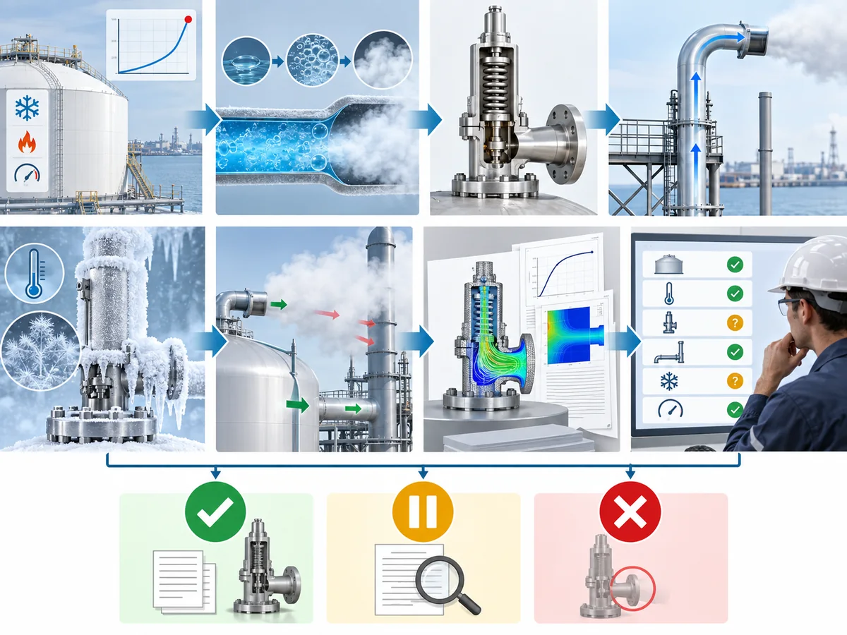
What Must Be Checked Before the LNG Discharge Arrangement Is Accepted?
A correctly sized valve does not automatically prove that the installed
discharge arrangement is acceptable.
API Standard 521
addresses pressure-relieving and depressurizing systems at LNG terminals
as well as other process facilities. That system-level scope is why valve
capacity and discharge-path review should remain connected.
1. Define the protected relief duty
Identify the protected equipment, credible overpressure scenario and
required relieving load. If the governing relief case is not established,
the remaining review rests on an undefined duty.
2. Establish the actual relieving condition
Confirm the process medium or mixture, relieving pressure, relieving
temperature and expected fluid state. Do not substitute normal storage
conditions for the relief-event condition.
3. Identify the exact valve configuration
Review the actual valve design and the components exposed to the
low-temperature condition. Body material or a family-level temperature
range does not define the complete valve configuration.
Component-specific review may be needed for trim, springs, seats, seals,
bellows and other temperature-sensitive parts. Exact suitability has to be
supported for the offered configuration rather than inferred from the
product family.
4. Trace the discharge route
Follow the outlet from the safety valve to the actual destination. Review
the places where the installed arrangement can introduce:
- physical restriction;
- moisture or liquid accumulation where applicable;
- an icing-sensitive termination;
- aufgebauten Gegendruck;
- superimposed back pressure from a connected system.
For the wider installation review—outlet support, drainage, piping stress,
orientation and commissioning—see the
Installationsanleitung für Sicherheitsventile
.
5. Confirm that icing-sensitive functions remain available
The review is not complete merely because frost has been identified. It
must determine whether the required valve movement and discharge passage
remain available under the defined condition.
6. Verify the low-temperature basis for the offered configuration
Check the supplier documentation for the exact construction being
proposed, rather than inferring suitability from a generic cryogenic label.
7. Verify outlet-pressure conditions independently
Resolve built-up and superimposed back pressure separately from physical
icing.
8. Do not close a critical unknown by assumption
If an unresolved variable could change capacity, valve operability,
low-temperature suitability or discharge-path availability, keep the item
open for engineering review.
FORTFAHREN, HALTEN und
ABLEHNEN, if used during this review, are screening terms
for the engineering workflow—not regulatory classifications.
What Information Should Go Into the Engineering Review or RFQ?
“LNG safety valve required” is not enough information for a defensible
technical review.
The project side should define the relief duty and installed conditions.
The supplier side should return configuration-specific evidence.
| Buyer / engineering team provides | Supplier / engineering team confirms |
|---|---|
| Protected equipment and credible relief scenario | Exact model and construction |
| Medium and relevant LNG composition | Materials for the offered configuration |
| Erforderliche Abblaseleistung | Seat, seal and other temperature-sensitive components where relevant |
| Set-pressure and relieving-pressure basis | Supported temperature limits |
| Entlastungstemperatur | Capacity basis for the defined duty |
| Liquid, vapour or two-phase basis | Suitability for the declared fluid-state basis |
| Inlet/outlet connection requirements | Applicable back-pressure limitations |
| Discharge destination and layout | Manufacturer outlet/discharge limitations |
| Built-up and superimposed back-pressure basis | Required test or conformity documentation |
| Minimum project temperature | Deviations and unresolved assumptions |
| Governing project/code basis | Evidence traceable to the offered configuration |
The procurement distinction is straightforward:
“Cryogenic service” describes a service category. It does not prove
that one exact valve configuration is suitable for the defined LNG relief
case.
Standards should be read with the same discipline.
ISO 4126-1
is a safety-valve product standard and explicitly is not an application
standard. A product-standard reference therefore cannot, by itself, prove
suitability for a particular LNG installation.
If pilot operation is being considered, review the pilot, sensing path and
seals separately. If back pressure is material to selection, resolve that
design question through the dedicated back-pressure review. If the
installed outlet arrangement is uncertain, resolve the installation before
treating the valve selection as complete.
For a project-specific review, prepare the defined relief duty, relieving
temperature and phase, outlet arrangement, back-pressure basis and required
documentation, then
Sicherheitsventilingenieur fragen.