应用选型博客 · 大孔径泄放阀评审 只有当主导泄放工况所需的泄放能力超过所选阀门配置中较小有效孔径所能提供的经确认泄放能力时,选用大孔径安全阀才具有合理性。“大孔径”必须指内部流通面积及经确认的排量依据,而不仅仅是较大的进口法兰,……

应用选型博客 · 大孔径泄放阀评审
只有当主导泄放工况所需的、有据可查的泄放能力超过所选阀门配置中较小有效孔径所能提供的能力时,选用大孔径安全阀才是合理的。“大”必须指内部流通面积和经核实的排量依据,而不仅仅是较大的进口法兰、出口法兰、DN 或 NPS。该决策会影响排量裕量、开启稳定性、背压响应、管道载荷、材料及项目验收。
报价前,请确认被保护设备、主导泄放工况、介质及相态、工作压力、MAWP 或设计压力、整定压力、适用时的冷态试验压力、所需泄放量、泄放压力与温度、叠加背压与积聚背压、进口压力损失、出口系统阻力、连接标准、材料及文件资料。在流程工业使用中,, PSV, PRV, SRV, 安全阀 和 泄压阀 可能用法不同;; PRV 也可表示减压阀。型号数据表、开启特性、流体基准、认证或额定排量以及规范标记——而非仅凭产品名称——决定其适用性。

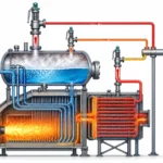
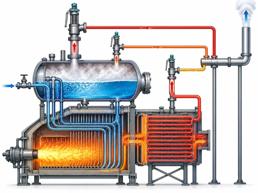
概念性工业示意图;非型号依据或认证证明。
快速解答
只有在已确定主导泄放工况的所需泄放量,并与具体型号的认证排量或文件化排量进行比对后,才应选用大孔径安全阀。连接尺寸、阀体尺寸和整定压力并不能确定有效孔径、排量系数、阀瓣升程或特定流体下的排量。蒸汽、空气或气体、液体及两相流的排量,在未采用相应计算方法和制造商数据的情况下不可互换。
当排量需求主导选型时,应进行大孔径评估。不得用更大规格的阀门来弥补未知的泄放工况、进口管道阻力过大、背压过高、运行不稳定或数据缺失。最终选型还必须核实工作裕量、材质、阀座结构、弹簧范围、进出口管道、排放反作用力、排放管路、项目采用的规范版本以及确切的制造商/型号配置。
何时应选用大孔径安全阀?
当主导工况的计算泄放负荷无法由合适阀门设计中较小的有效孔径承担时,应考虑选用大孔径安全阀。典型驱动因素包括蒸汽或气体质量流量大、火灾工况、出口堵塞、压缩机或调节阀故障、管束破裂,或其他项目定义的异常工况。在使用阀门样本之前,必须先确定该工况。
选型必须在正确的流体基准、整定压力、超压、泄放压力和温度下,将所需泄放量与所选阀门的额定排量或认证排量进行比对。实际孔径、有效孔径、阀瓣升程、系数和开启特性均属型号级数据。两台进口和出口尺寸相同的阀门,其内部流道、弹簧范围和背压限值可能不同。
关于确定设备限值、工况和阀门系列的更完整流程,请使用 ZOBAI 安全阀选型指南. 。本指南重点说明何时大有效孔径在技术上合理,以及该决策需要哪些依据支持。
| 情况 | 为何可能需要大孔径评估 | 必须确认的内容 |
|---|---|---|
| 所需泄放量高 | Smaller orifice may not pass the governing load. | Required relieving capacity, fluid properties and relieving pressure. |
| Large steam or gas relief | High mass flow can require larger effective area. | Steam/gas data, set pressure, overpressure and discharge path. |
| Fire case on vessel or system | Required load may be driven by external fire exposure. | Protected equipment, wetted area basis and project code. |
| Compressor or process upset | Flow demand can be high and dynamic. | Scenario basis, back pressure and piping response. |
| Replacement of an old large valve | Appearance and flange size may not prove capacity. | Nameplate, datasheet, capacity basis and installation. |
Selection Boundary: When Large Orifice Is Appropriate and When It Is Not
A large effective orifice is appropriate when capacity evidence drives the choice and the selected valve can operate stably in the installed system. It is not a corrective shortcut for poor inlet layout, excessive outlet resistance, insufficient operating margin, an undefined two-phase case or incomplete replacement data. Increasing flow area without checking the whole pressure-relief system can increase cycling, chatter, reaction load, seat damage and cost.
| 问题 | Large Orifice Review May Be Appropriate When… | Do Not Use Large Orifice as a Shortcut When… |
|---|---|---|
| 排量 | The required relieving capacity cannot be met by a smaller effective orifice under the selected service conditions. | The required capacity is unknown or the inquiry only provides DN/NPS and set pressure. |
| 压力数据 | Operating pressure, MAWP/design pressure, set pressure and relieving pressure are defined. | Set pressure is being used as a substitute for capacity or design basis. |
| 背压 | Outlet pressure has been estimated and valve configuration can be reviewed. | Back pressure is excessive or unknown and the buyer assumes a bigger valve will solve it. |
| 安装 | Inlet loss, outlet support, drainage and reaction force are considered in the piping design. | The inlet is restrictive, the outlet is unsupported or discharge routing is unsafe. |
| 更换 | The old valve nameplate, datasheet, capacity basis and service condition are available. | The replacement is based only on visual appearance, flange size or an old photo. |
重要边界: Oversizing or increasing orifice size without confirming the relief scenario, operating margin, inlet loss and discharge system can create new stability, leakage, cost and installation risks. A larger valve is not automatically a safer valve.
Start With the Protected Equipment and Relief Scenario
Large-orifice selection begins with the protected equipment and the credible overpressure scenario. Identify whether the device protects a boiler, pressure vessel, exchanger, compressor package, reactor, pipeline, storage system, pump discharge or process skid. The equipment code and project basis determine which scenarios and pressure limits must be evaluated.
Blocked outlet, fire exposure, regulator failure, tube rupture, thermal expansion and process upset do not produce the same load, phase behavior or relieving temperature. The governing case is the case that controls required capacity or another critical selection condition; it must not be inferred from the old valve size.
System-level scenario and disposal-system questions belong in the API 521 压力泄放系统 topic. This page uses the scenario only to establish whether a large effective orifice is needed.
工程边界: The key question is not “What is the valve size?” The key question is “What relief case must this valve safely pass?”
Composite Engineering Scenario: Competing Relief Cases
In a composite engineering scenario, a vessel has both blocked-outlet and external-fire cases. The buyer submits the old valve size and set pressure, but not the calculated loads. The observed problem is an apparently “large” valve with no traceable governing case. The engineering cause is an incomplete relief basis, not a confirmed need for more area. The corrective action is to identify the governing load, phase, relieving pressure and temperature, then compare required capacity with model-specific data. The preventive control is to retain the relief calculation and scenario revision history with the valve datasheet. This is an illustrative training case, not a customer project or performance claim.
Required Relieving Capacity vs Selected Orifice vs Documented Capacity
Large-orifice selection requires four separate checks: required relieving capacity, calculated required area, selected effective orifice and manufacturer-supported rated or certified capacity. Actual bore and connection size are additional physical dimensions; neither substitutes for the effective area and coefficient used in the capacity basis.
Required relieving capacity comes from the governing scenario. The required area is calculated using the applicable fluid method and conditions. The selected effective orifice is the standardized or model-specific flow area offered by the manufacturer. Rated or certified capacity is the supported performance of the exact configuration under stated conditions. These values must be compared on the same medium, pressure, temperature and coefficient basis.
For calculation detail, use 安全阀定径和认证泄放能力 and the separate API 520 sizing page. This article does not reproduce sizing equations or claim capacity for an unspecified model.

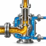
Simplified engineering illustration; not a sizing calculation sheet or certified capacity record.
| 术语 | 含义 | Selection Risk if Misused |
|---|---|---|
| 所需泄放量 | The capacity the system must relieve under the governing case. | If missing, the valve may be selected by size only. |
| Required area / selected orifice | The flow area needed to pass the required load. | If guessed, the valve may be oversized or undersized. |
| 认证排量或文件化排量 | Capacity supported by manufacturer data, test basis or applicable standard context. | If not verified, the valve may fail project acceptance. |
| 连接尺寸 | Inlet/outlet interface to piping. | It does not prove the effective orifice or capacity. |
| 整定压力 | Pressure at which the valve is set to open. | It is not the same as capacity. |
Capacity Evidence Review Path
- Confirm the governing relief case. The valve should be selected for the case that determines the required relieving capacity.
- Confirm the required relieving capacity and basis. State whether the capacity comes from a process safety calculation, project datasheet, replacement record or preliminary estimate.
- Review the selected orifice or effective flow area. The orifice must be checked against the medium, relieving pressure, temperature and valve configuration.
- Check documented or certified capacity. Final selection depends on manufacturer-supported data for the selected model and applicable specification.
- Verify installation and back pressure. A capacity match is not complete if inlet loss, outlet back pressure or discharge support is not acceptable.
Opening Characteristic, Lift and Seat Design Are Model-Level Data
Large effective area does not by itself describe how the valve opens. Pop-action, proportional-lift, full-lift and low-lift designs can respond differently to fluid service, available flow, operating margin and back pressure. Metal seats and soft seats also have different temperature, compatibility, tightness and maintenance boundaries. Confirm the actual opening characteristic, lift basis, seat construction and manufacturer limits for the selected model.
复合工程工况: A replacement valve matches the old inlet and outlet sizes, but its effective orifice and lift characteristic differ. The observed issue is rapid cycling at a low actual relief demand. The likely engineering cause is a capacity and dynamic mismatch, not a flange mismatch. The corrective action is to compare required load, old and new capacity data, effective orifice, lift and operating trend. The preventive control is to prohibit size-only substitution in the management-of-change process. This is an illustrative training scenario, not a field record.
Connection size alone does not prove capacity. A larger inlet flange can serve mechanical or standardization needs while the internal nozzle remains smaller; a larger outlet can be required for discharge hydraulics without changing the inlet effective area. A process debottleneck, increased heat input, new feed composition or revised relief scenario requires the capacity basis to be rechecked even when the installed connections remain unchanged.
Confirm Pressure Data Before Choosing the Orifice
Pressure definitions must be kept separate because they affect opening, capacity, stability, test adjustment and equipment protection. A quotation that lists only set pressure is incomplete for large-orifice selection.
Operating pressure describes normal and maximum expected service pressure. MAWP is the maximum allowable working pressure of the protected equipment under its governing code basis; design pressure may be used differently by the project and should not be assumed identical without review. Set pressure is the specified opening setting. Cold differential test pressure (CDTP), when used, is the shop-test setting adjusted for service factors such as temperature or back pressure according to the applicable basis. Overpressure, accumulation and relieving pressure are related but not interchangeable. Blowdown and reseating pressure affect closure and process recovery, while operating margin affects leakage and cycling risk.
| Pressure Data | Why It Matters for Large Orifice Selection | Need User Confirmation? |
|---|---|---|
| 工作压力 | Affects leakage margin and normal stability. | Yes, especially if close to set pressure. |
| MAWP / 设计压力 | Defines protection basis for the equipment. | Yes, from vessel/system design documents. |
| 整定压力 | Determines opening point and must match project requirement. | Yes, with units and tolerance requirement. |
| 超压 / 压力积聚 | Affects relieving pressure and capacity basis. | Yes, subject to applicable code and scenario. |
| 泄放压力 | Used in capacity evaluation. | Yes, if capacity review is requested. |
| Reseating pressure / blowdown | May affect operating stability and process recovery. | Project dependent. |
| Flange pressure-temperature rating | Must remain suitable at design and relieving conditions. | Yes, with material group and connection standard. |
| 冷态试验压差(CDTP) | Links shop test adjustment to stated service corrections; it is not automatically equal to field set pressure. | Confirm only when the project or manufacturer basis uses CDTP. |
| 工作压力裕量 | Affects simmer, leakage, cycling and stable operation below set pressure. | Confirm normal and maximum operating pressure; do not assume a universal margin. |
Do not apply one universal percentage for operating margin, overpressure, accumulation, blowdown or inlet loss. The permitted values depend on the equipment code, relief scenario, fluid, valve design, project-adopted edition and manufacturer limits. Pressure-temperature rating must also be checked at design and relieving temperatures; see 压力-温度额定值 for the separate flange/material topic.
Check Medium, Phase and Relieving Temperature
Fluid service controls the calculation method, required area, opening behavior, discharge reaction, materials and test basis. Steam, air or gas, vapor, liquid and two-phase loads are not interchangeable merely because set pressure and connection size are the same.
Steam service can require attention to temperature, drainage and bonnet arrangement. Gas and vapor service can create high velocity and reaction force. Liquid service can be sensitive to viscosity, cavitation, flashing and stability. Two-phase service requires a method appropriate to the process behavior. Dirty, polymerizing or crystallizing fluids can obstruct the nozzle, guide, pilot passages or sensing lines.
| 使用工况 | 需确认的数据 | Selection Impact |
|---|---|---|
| 蒸汽 | Pressure, temperature, dryness, discharge route. | Bonnet, seat, drainage, capacity and installation. |
| Gas / vapor | Molecular weight, relieving temperature, back pressure. | Orifice, outlet size, reaction force, capacity basis. |
| 液体 | Density, viscosity, allowable overpressure, discharge handling. | Stability, trim, seat and outlet handling. |
| 两相 | Phase behavior, calculation method, process data. | Requires careful engineering review. |
| Corrosive media | Concentration, temperature, contaminants. | Body, bonnet, nozzle, disc, guide, spindle, spring, bellows, gasket and seat materials. |
| Viscous or dirty media | Viscosity, solids, fouling tendency. | Nozzle/guide fouling, seat damage, pilot sensitivity, maintenance and configuration. |
| 高温或低温 | Relieving temperature, material rating. | Body, spring, seat, seal and flange rating. |
Material review must cover the parts actually exposed or functionally affected: body, bonnet, nozzle, disc, guide, spindle, spring, bellows, gasket, packing, soft seat and O-ring. Upgrading only the body does not control corrosion, galling, stress-corrosion cracking, sticking, seal degradation or spring instability in the other components. Sour-service requirements such as NACE MR0175 / ISO 15156 should be invoked only when the service and project require them, and final materials must be confirmed for the selected model.
Evaluate Back Pressure Before Selecting Conventional, Bellows or Pilot Designs
Back pressure must be evaluated before selecting the valve configuration because a large relief load can create substantial outlet pressure and mechanical load. The outlet connection and header are part of the pressure-relief system, not merely discharge accessories.
Superimposed back pressure exists before opening and may be constant or variable. Built-up back pressure is generated by relief flow through the outlet system. Both can affect opening pressure, lift, capacity and reseating. Outlet system resistance, simultaneous discharges, silencers, flare or scrubber pressure, drainage and liquid pockets must be included in the review.
Use the dedicated 背压与波纹管 page for mechanism and configuration detail. This page only establishes the data boundary for large-orifice selection.

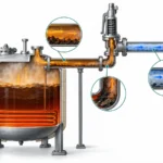
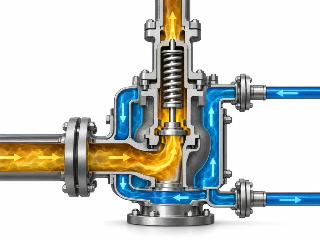
Simplified engineering illustration; final valve configuration depends on service data and manufacturer limits.
| 背压工况 | Possible Review Direction | Data Needed |
|---|---|---|
| Low and stable outlet pressure | Conventional design may be reviewed. | Outlet line layout and allowable back pressure. |
| 可变附加背压 | Balanced or pilot design may need review. | Minimum and maximum back pressure values. |
| 较高的积聚背压 | Outlet piping and valve configuration review required. | Discharge calculation, header pressure and flow path. |
| Shared discharge header | Interaction with other relief devices must be checked. | Header design and simultaneous relief assumptions. |
| Corrosive or high-temperature outlet service | Bellows/material review may be critical. | Medium, temperature and corrosion data. |
复合工程工况: A high-capacity valve becomes unstable after a silencer and common header are added. The observed issue is cycling and increased vibration during discharge. The likely causes are increased built-up back pressure, variable header pressure and added mechanical load. The corrective action is to calculate the revised outlet pressure, review simultaneous relief assumptions, support and drainage, then reassess the valve configuration. The preventive control is to include relief-header modifications in management of change. This is an illustrative scenario, not a customer incident.
A conventional spring-loaded, balanced-bellows or pilot-operated valve should be selected from quantified conditions and model limits. A bellows requires correct bonnet vent routing and material review. Pilot-operated designs can be sensitive to sensing-line blockage, condensation, freezing, polymerization and maintenance quality. Neither configuration is a universal cure for unknown or excessive back pressure.
Review Inlet Pressure Loss, Outlet Piping and Reaction Force
Large-orifice valves can produce high flow, discharge reaction and piping loads. Installation review must therefore connect hydraulic performance with mechanical integrity.
The inlet should be clean, direct and adequately sized for the selected device and relief case. Excessive inlet pressure loss can reduce the pressure available at the valve after opening and contribute to flutter or chatter. The outlet must be checked for resistance, support, thermal movement, reaction force, safe routing, drainage and liquid pockets. Heavy piping or misalignment must not transfer unacceptable load into the valve body or connections.
This page does not own detailed installation or chatter diagnosis. Use the 安全阀安装指南 for that review, while retaining the installation results as selection inputs.

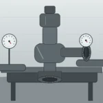
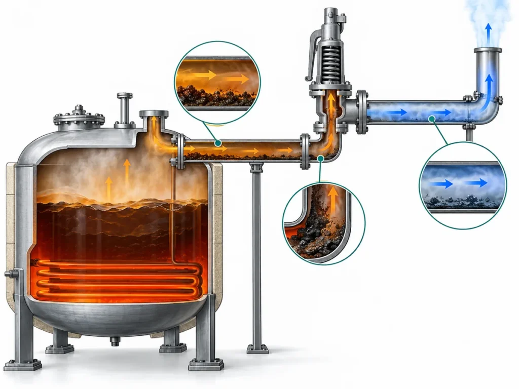
Simplified engineering illustration; actual installation must follow project piping design and applicable code requirements.
| 安装检查 | 重要性 | What to Avoid |
|---|---|---|
| 入口压力损失 | Can affect valve stability and capacity delivery. | Long, restrictive or reduced inlet piping without review. |
| Inlet line size and layout | Long or restrictive inlet piping can create pressure drop. | Multiple elbows, restrictions or dead legs close to the inlet. |
| Outlet back pressure | Can affect capacity and opening behavior. | Unknown or variable back pressure ignored in selection. |
| Outlet support | Prevents mechanical load from being transferred to the valve body. | Heavy outlet piping hanging from the valve. |
| Reaction force | Important for large discharge rates. | No piping/support review for high-flow discharge. |
| 排液 | Avoids liquid accumulation and corrosion risk. | Liquid pockets or blocked discharge paths. |
| 安全排放方向 | Protects personnel and surrounding equipment. | Discharge toward personnel, walkways or vulnerable equipment. |
For replacement work, do not accept the existing piping as correct solely because a valve has operated there. Compare current layout, process load and outlet system with the original design. Check orientation, isolation-valve controls, inlet cleanliness, outlet support, drainage, bonnet vent routing where applicable, and evidence of vibration or leakage before approving a like-for-like replacement.
Match the Connection Standard to Capacity, Piping and Project Requirements
Connection data confirms mechanical fit and pressure-temperature suitability; it does not establish effective orifice or capacity. Specify inlet and outlet size separately, flange standard, class or PN rating, facing, material group, bolting/gasket requirements and project dimensional constraints.
Large-capacity valves are often flanged because of size, maintenance and piping requirements, but the sequence remains: establish required capacity, select a suitable valve configuration and effective orifice, then verify that the offered connections fit the project. Reversing that sequence encourages size-only selection.
使用 ASME B16.5 法兰尺寸 for the separate flange interface topic and API 526 法兰安全阀 for standardized API orifice designations and dimensions. API 526 standardization does not replace the relief calculation or prove that a specific manufacturer/model/configuration has the required capacity.
| Connection Data | 需要该数据的原因 |
|---|---|
| Inlet size and standard | Confirms piping interface and flange compatibility. |
| Outlet size and standard | Affects discharge piping and back pressure. |
| Pressure class or PN rating | Must suit pressure-temperature conditions. |
| 密封面型式 | Needed for gasket and installation compatibility. |
| 材料组别 | Affects pressure-temperature rating. |
| Existing dimensions | Important for replacement and skid layout. |
| Project standard | Determines inspection, documentation and acceptance requirements. |
API, ASME, ISO, EN, DIN, GB and project specifications have different scopes. A reference can govern sizing, product design, dimensions, testing, marking or documentation, but no standard name substitutes for a complete datasheet and model-specific evidence.
Selection Workflow for Large Orifice Safety Valve RFQ
A reviewable RFQ must show why a large effective orifice is being considered and provide enough data to compare required and offered capacity. “Large orifice safety valve, DN size, set pressure and quantity” is not a complete selection basis.

Checklist graphic for inquiry preparation; not a final sizing sheet or certified capacity document.
| 询价数据 | 所需信息 |
|---|---|
| 受保护设备 | Vessel, boiler, compressor, pipeline, heat exchanger, skid, reactor or other system. |
| 泄放工况 | Blocked outlet, fire case, regulator failure, tube rupture, thermal expansion or other scenario. |
| 介质及相态 | Steam, gas, vapor, liquid, two-phase, corrosive, viscous, dirty or special service. |
| 工作压力 | Normal pressure range. |
| MAWP / 设计压力 | Equipment design basis. |
| 整定压力 | Required valve set point. |
| 所需泄放量 | Flow rate and basis, if available. |
| 泄放温度 | Temperature during relief event. |
| 背压 | Superimposed and built-up values, if known. |
| 连接 | Inlet/outlet size, standard, class/PN and facing. |
| 材料 | Body, trim, seat, spring, bellows or special material requirements. |
| 适用标准 | API, ASME, ISO, EN/DIN, GB or project specification, where applicable. |
| 文件资料 | Datasheet, test reports, material records, inspection or witness requirements. |
RFQ Data Readiness
不完整
Connection-only inquiry
DN/NPS, flange class, set pressure and quantity are provided, but required capacity and service evidence are missing.
可供审查
Preliminary engineering review
Equipment, scenario, medium, pressure, temperature and connection data are available, but the required load or back-pressure basis still needs confirmation.
Ready for technical review
Capacity-supported review
Required load, calculation basis, back pressure, installation, materials and document requirements are available for model-level comparison.
For replacement valves, add nameplate and installation photos, old datasheet, capacity basis, general arrangement drawing, flange details, as-found test data, maintenance history and process or piping changes. Unknown values should be marked “to be confirmed,” not guessed. If the old valve leaked, cycled, chattered or failed inspection, report the symptom without assuming the cause.
Replacement Review Workflow for an Existing Large Valve
Replacement is a revalidation task, not a dimensional copy. Changes in throughput, composition, heat input, control philosophy, relief header, equipment MAWP, applicable code edition or maintenance configuration can invalidate the old selection even when the same DN/NPS and set pressure are retained.
- Collect identification without over-interpreting it. Record nameplate, model, serial number, set pressure, size, material and markings; a marking does not prove all required capacity or project acceptance.
- Collect the engineering basis. Obtain the old datasheet, relief calculation, certified or rated capacity, effective orifice, test records and project specification where available.
- Confirm current service and management of change. Check medium, phase, operating pressure, MAWP, scenario, throughput, temperature and discharge-system changes.
- Review installation and valve condition. Record inlet/outlet layout, support, drainage, back pressure, corrosion, deposits, leakage and as-found condition.
- Approve the replacement from model-specific evidence. Compare required load, capacity basis, opening characteristic, spring range, materials, dimensions and documentation before ordering.
复合工程工况: A plant expansion increases the blocked-outlet load, but procurement requests the same valve size because the existing unit passes a set-pressure test. The observed evidence confirms opening setting only. The engineering gap is that set-pressure testing does not demonstrate adequate capacity for the revised load. The corrective action is to recalculate the scenario and verify model-specific capacity and installation. The preventive control is to trigger pressure-relief revalidation whenever process capacity changes. This is an illustrative training scenario.
替换警告: Matching old DN/NPS, flange class and set pressure does not prove the replacement valve will protect the same equipment. Capacity basis, service condition, materials, installation and applicable standard must still be reviewed.
Test and Document Matrix for Engineering Review
Documents must be requested by purpose. A set-pressure calibration record confirms adjustment under stated test conditions; a seat-tightness test addresses leakage acceptance; capacity certification or rated-capacity data supports flow performance. None of these documents substitutes for the others, and none proves that the installed system has acceptable inlet loss or back pressure.
| 文件/核查项目 | 重要性 | Need to Confirm Before RFQ |
|---|---|---|
| 阀门数据表 | Defines size, pressure, material, configuration and connection data. | Yes, especially for project approval. |
| 排量基准 | Supports comparison of required load with rated or certified performance for the exact configuration and fluid basis. | Yes, for large-orifice selection. |
| 整定压力校验 | Confirms the pressure setting under the stated test medium and conditions; it is not a capacity test. | Yes, with tolerance and test medium where applicable. |
| Seat tightness / leakage test | Supports leakage acceptance, for example under API 527 seat-tightness where the project adopts it; it is not a sizing standard. | Project dependent. |
| 材质记录 | Supports body, trim, spring, bellows or special material requirements. | Yes, if material traceability is required. |
| Inspection / witness scope | Defines third-party, customer or internal inspection requirements. | Yes, before quotation if required. |
| Existing nameplate and photos | Useful for replacement review and dimensional matching. | Yes, for replacement inquiries. |
| As-found / as-left and repair traceability | Shows condition before work, final setting, parts changed, spring range, resealing/nameplate status and repair control. | Confirm for maintenance or replacement scope. |
| NB-18 / certification-directory check | Can verify listed manufacturer, device type and certified configuration where applicable; it does not approve the project sizing or installation. | Confirm only when the project requires this certification route. |
Where repair is governed by the National Board Inspection Code and a VR authorization route, verify the repair organization’s current scope and the adopted NBIC edition. VR authorization controls the repair quality system; it does not replace relief sizing, model selection, management of change or installed-system review.
Common Selection Mistakes to Avoid
Selecting by nominal size alone
DN/NPS and flange dimensions confirm fit-up, not the effective orifice, lift, coefficient or capacity.
将整定压力等同于排量
A correct opening setting does not prove the valve can pass the governing relief load.
Ignoring system hydraulics
Unknown inlet loss or back pressure can invalidate an otherwise adequate capacity selection.
Replacing by appearance or marking
Nameplates and markings support identification but must be matched to current service, capacity evidence, materials and installation.
标准与选型限制
Standards are evidence for defined scopes, not a substitute for engineering. API 520 Part I addresses refinery pressure-relief sizing and selection; API 521 addresses relief and depressuring systems; API 526 standardizes specified flanged steel PRV dimensions and effective-orifice designations; ASME BPVC Section XIII provides overpressure-protection rules; ISO 4126-1 is a safety-valve product standard and explicitly is not an application standard. Verify the edition adopted by the project and the exact manufacturer/model certification before making compliance claims.
Engineering References to Confirm
The official pages below were checked during the technical review on 2026-07-20. Published editions and documents in development are distinguished; the project must still verify its contractually adopted edition.
- API 520 第I部分,第10版 — published sizing and selection standard; API lists an 11th edition in development.
- API Standards Plan: API 521 and API 526 — lists API 521 7th Edition and API 526 8th Edition as published, with later editions in development.
- ASME BPVC 第XIII卷,2025 — overpressure-protection rules, including capacity certification and installation scope.
- ASME B16.5, 2025 — flange pressure-temperature ratings, dimensions, materials, marking and testing scope.
- ISO 4126-1:2013 with Amendment 1:2016 — general safety-valve product requirements; ISO states that it is not an application standard.
- 美国国家锅炉与压力容器检验师协会 NB-18 — current searchable certification database for manufacturers, assemblers and certified device types.
FAQ About Large Orifice Safety Valve Selection
“大孔径安全阀”是什么意思?
这意味着所选阀门具有有效的流通面积和特定型号的排量,能够满足较高的所需泄放负荷。这并不仅仅意味着阀体、进口法兰、出口法兰、DN或NPS尺寸较大。
何时需要大孔径泄压阀?
当主导泄放工况和计算表明,在合适的阀门配置下,较小的有效流道面积无法提供所需泄放量时,应考虑选用大孔径安全阀。请确认介质条件、压力、温度、背压及制造商数据。
我可以根据整定压力和连接尺寸来选择安全阀吗?
序号 整定压力确定开启设定值,连接尺寸确定安装配合。选型还需考虑主导泄放负荷、有效流道面积、额定或认证排量、介质、泄放工况、背压、材质及安装审查。
有效流道面积与实际流道直径相同吗?
不一定。有效流道面积是用于排量计算基准或标准化代号中的面积,而实际流道直径是物理尺寸。请以制造商数据表及所选型号适用的标准定义为准。
背压是否会影响大孔径安全阀的选型?
是的。叠加背压和排放背压会影响开启、升程、排量和回座。常规式、波纹管平衡式和先导式设计必须根据量化条件和型号限制进行校核。
较大孔径会导致安全阀频跳吗?
当所选排量与可持续泄放流量匹配不佳,或入口压损、运行裕量或出口背压不利时,可能引发频跳。频跳需要进行系统审查,而非简单调整阀门。
大孔径安全阀询价应提供哪些文件?
请提供泄放工况及所需泄放量、阀门数据表、排量基准、压力与温度数据、背压与管道信息、材质、连接方式、适用规范版本以及所需的试验或检验记录。
能否根据旧铭牌照片进行替换审批?
编号。铭牌有助于识别,但当前工况、泄放工况、所需泄放量、有效排放面积、材质、安装、维护历史及项目要求也必须重新核实。
Ask ZOBAI to Review Your Large Orifice Safety Valve Conditions
Send the protected equipment, governing relief scenario, required relieving capacity and calculation basis, medium and phase, operating pressure, MAWP or design pressure, set pressure and CDTP where applicable, relieving pressure and temperature, superimposed and built-up back pressure, inlet/outlet piping, connection standard, materials and required documents. For replacement work, include the old datasheet, nameplate, installation photos, as-found records and process or piping changes.