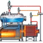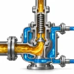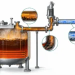
安全阀定径是确定可信超压工况下必须泄放多少流量,并选择具有足够经认证排量以保护设备的安全阀的过程。它并不等同于选择进出口连接尺寸相同的安全阀。安全阀可能匹配接管口径、匹配……

安全阀定径是确定可信超压工况下所需泄放流量,并选择具有足够验证排量以保护设备的安全阀的过程。它并不等同于选择进出口连接尺寸相同的阀门。
阀门可能与接管匹配、法兰等级相符,并在正确的整定压力下开启,但如果其认证泄放能力低于所需泄放负荷,仍然属于选型偏小。因此,正确的定径应从被保护设备和主导泄放工况出发,而不是从库存阀门型号出发。
工程要点: 整定压力说明阀门何时开始开启。所需泄放能力说明系统必须排放多少流量。认证泄放能力表明所选阀门设计在给定基准下能否提供足够的经验证流量。
本指南范围: 本页重点介绍泄放负荷输入、定径流程、孔径选择及认证能力验证。如需涵盖阀门类型、材料、密封面设计、安装和采购的更全面决策,请使用 安全阀选型指南. 。如需 API 520 的具体要求及询价文件解读,请使用 API 520 安全阀定径指南.
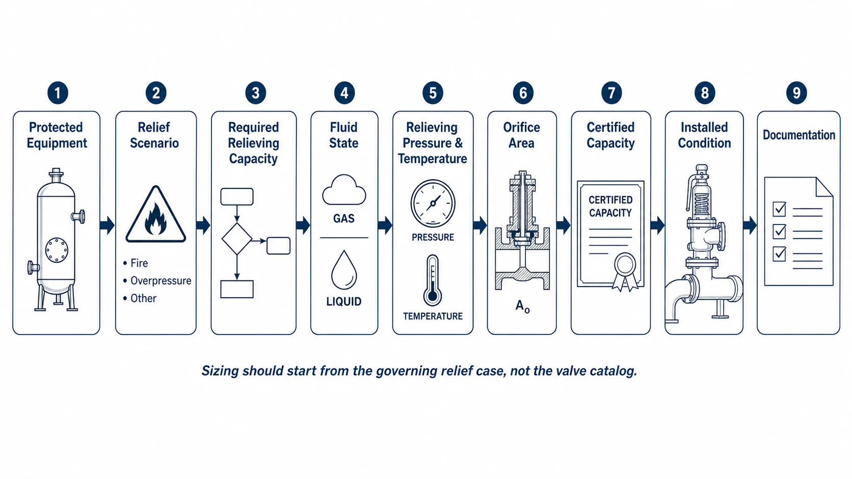
如何计算安全阀尺寸?
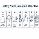
在实际操作层面,安全阀选型按以下顺序进行:
被保护设备 → 可信泄放工况 → 控制泄放负荷 → 泄放压力与温度 → 流体物性 → 所需泄放面积 → 下一合适阀门口径 → 认证排量 → 安装工况复核
- 确定被保护设备。 确认设备位号、MAWP、设计压力、工作压力及适用规范依据。
- 识别所有可信的超压工况。 例如出口堵塞、外部火灾、调节阀故障、管束破裂、热膨胀及冷却失效。
- 确定控制性的所需泄放量。 最大可信工况并不总是控制工况;控制工况取决于完整的定径依据和允许条件。
- 确认泄放条件。 说明泄放压力、泄放温度、介质组成和流体相态。
- 计算所需流通面积。 采用适用的规范方法、工艺数据和修正系数。
- 选择制造商或标准化孔径。 选择满足所需面积和使用限制的孔径。
- 核实认证排量。 所选装置必须针对所述使用依据提供足够的认证排量或有据可查的排量。
- 审查已安装系统。 检查入口损失、背压、出口阻力、排放路径和同时泄放工况。
请勿将本文作为最终计算书使用。 最终定径必须采用项目要求的规范版本、经确认的工艺数据、现行制造商认证系数与排量资料,并经责任工程师批准。
为什么安全阀定径不等于选择连接尺寸
进口和出口尺寸描述阀门如何与设备和排放系统连接。它们并不定义内部流通面积,也不能证明阀门能够排放所需的泄放量。
实际泄放性能受以下因素影响:
- 有效或实际泄放面积;;
- 阀瓣升程与内部流道;;
- 认证排量系数;;
- 整定压力与绝对泄放压力;;
- 流体相态与物性;;
- 泄放温度;
- 叠加背压与积聚背压;;
- 黏度、压缩性或蒸汽修正系数;;
- 适用时,包括爆破片组合系数;;
- 制造商认证排量及认证依据。
两台阀门即使都标注为 2 in × 3 in,其孔径代号、升程、排量系数和认证排量仍可能不同。因此,同尺寸替换并不自动意味着排量等效。
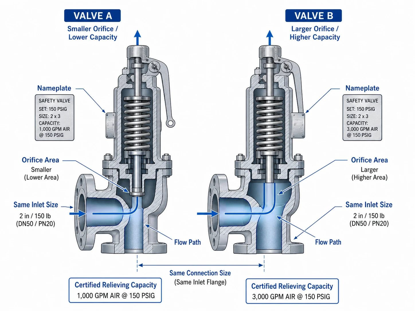
替换警告: 不得仅凭型号外观、法兰尺寸或压力等级批准替换。应对比原始定径依据、孔径代号、排量依据、认证排量、整定压力、背压工况及铭牌信息。
安全阀定径输入参数 60 秒检查清单
在开始计算或提交供应商审核之前,请确认以下信息是否齐备。缺失数据应明确列出,不得以默认假设替代。
受保护设备: 压力容器、锅炉、换热器、压缩机、管道或橇装系统
压力限值: MAWP、设计压力及适用规范限值
运行数据: 常温常压
整定压力: 包括任何多阀配置
泄放工况: 所有可信的超压原因
所需流量: 带单位和基准的质量流量或体积流量
介质: 组分、分子量、密度或蒸汽状态
流体相态: 气体、蒸气、蒸汽、液体、闪蒸或两相
泄放条件: 阀门入口处的压力和温度
背压: 叠加背压、积聚背压和总背压
安装: 进口损失、出口管道、集管、消音器及排放点
合规性: 规范版本、认证、检验及文件资料
当这些输入信息不完整时,请通过以下方式提交现有数据表、P&ID、设备图纸、旧阀铭牌及出口草图 工程师咨询 以便在报价前识别缺失信息。
安全阀定径、选型与 API 标准:应使用哪个页面?
将定径、选型、标准与应用指南清晰区分,可避免技术混淆。这些 ZOBAI 资源用途不同:
| 资源 | 主要问题 | 主要范围 |
|---|---|---|
| 安全阀定径指南 | 需要多大排量和孔径面积? | 泄放负荷、所需面积、认证排量、定径输入及审批检查。 |
| 安全阀选型指南 | 应选用哪种阀门类型和配置? | 阀门类型、介质、背压、材质、阀座、安装及采购。 |
| API 520 指南 | API 520 在过程工业定径与询价中如何使用? | API 520 第 I 部分背景、输入因素、询价数据及安装审查相关链接。 |
| API 521 指南 | 需要评估哪些泄放工况和排放系统条件? | 火灾工况、泄放系统设计、火炬总管、降压及系统级载荷。 |
| API 526 指南 | 标准化法兰连接 PSV 的孔径和尺寸如何表示? | 孔径代号、法兰尺寸、压力等级、尺寸及采购信息。 |
什么是所需泄放量?
所需泄放量 是指在起支配作用的可信超压工况下必须泄放的流量,以使被保护设备保持在适用压力限值以内。
该数值来自系统与泄放工况,而非阀门样本。供应商可在收到计算依据后协助匹配设备,但产品型号本身无法确定泄放负荷。
所需泄放量来自泄放工况
| 泄放工况 | 典型负荷机理 | 需核查的关键数据 |
|---|---|---|
| 出口堵塞 | 正常排放被阻断时,进料流量仍在持续。 | 最大可信进料量、上游压力及控制行为。 |
| 外部火灾 | 热量输入导致蒸气产生、气体膨胀或压力升高。 | 润湿面积、热量输入依据、保温或防火层折减及流体物性。 |
| 热膨胀 | 封闭液体随温度升高而膨胀。 | 封闭容积、热源、液体膨胀及泄放去向。 |
| 控制阀或调节阀失效 | 较高上游压力或流量进入较低压力等级设备。 | 上游来源、失效位置、最大压差及下游排放能力。 |
| 换热器管束破裂 | 高压流体进入低压侧。 | 管径、压差、相态变化及下游响应。 |
| 气体窜漏 | 气体进入低压容器或液体系统。 | 节流结构、上游工况及下游相态变化。 |
| 冷却或公用工程中断 | 热量移出停止或过程控制失效。 | 反应或蒸气生成速率、热量输入及升级时间。 |
| 化学反应 | 反应热或气体生成导致压力升高。 | 动力学、放热、气体生成、两相行为及应急响应。 |
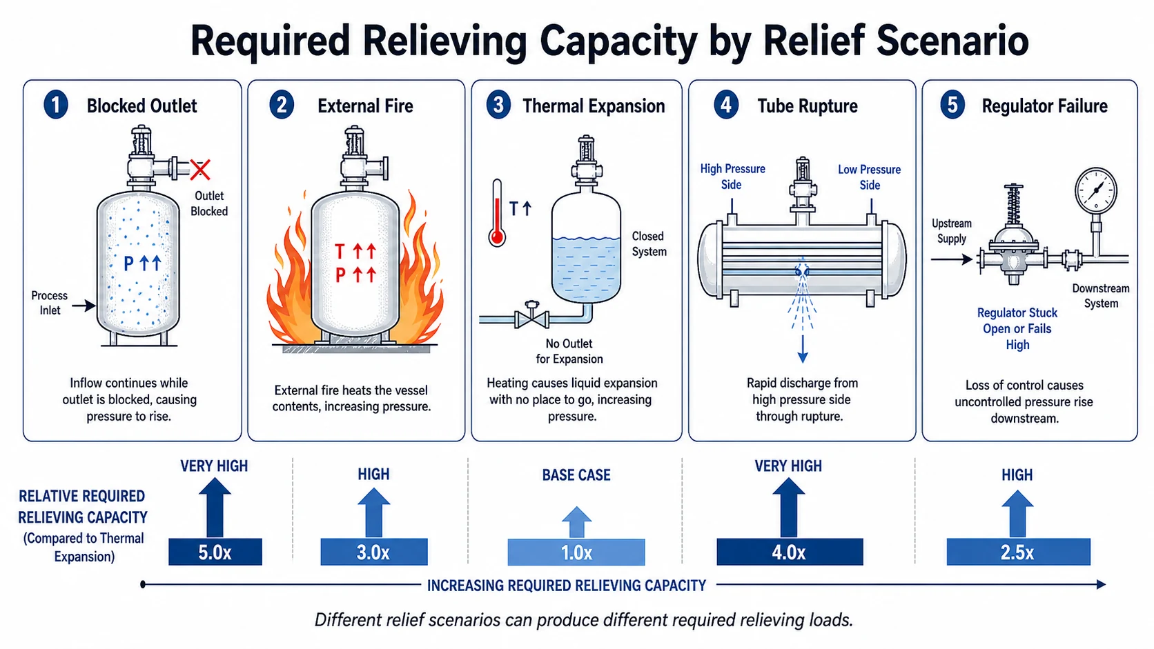
可能需要记录多个工况。所需公称流量最大的工况并不自动是唯一重要工况,因为流体相态、背压、允许超压、多阀配置规则及排放系统行为可能改变控制阀门或安装要求。
什么是认证泄放能力?
认证泄放能力 是与特定压力泄放装置设计和认证依据相关的经验证的排量值。它使工程师、采购人员、检验人员及设备业主能够将所选装置与所需泄放量进行对比。
在适用的 ASME 和国家锅炉与压力容器检验师协会(National Board)语境下,认证装置信息可通过官方 国家锅炉与压力容器检验师协会 NB-18 压力泄放装置认证资源. 国家锅炉与压力容器检验师协会还通过其 泄压实验室.
Required Capacity, Calculated Capacity, Rated Capacity and Certified Capacity
| 术语 | 含义 | 批准前的问题 |
|---|---|---|
| 所需泄放量 | The flow the protected system must discharge during the governing case. | What does the process or equipment require? |
| Calculated capacity | A result derived from a sizing equation, conversion or manufacturer tool for specified conditions. | Were the correct inputs, equation and correction factors used? |
| 额定排量 | A capacity stated for a valve under defined rating conditions. | What conditions and factors support the rating? |
| 认证泄放能力 | A capacity verified under the applicable certification framework for the device design. | Is the value traceable to the exact model, orifice, set pressure and capacity basis? |
| Installed performance | The behavior of the valve after inlet loss, back pressure and discharge-system effects are considered. | Will the certified device remain suitable in the real piping system? |
Capacity basis matters: A certified air, saturated-steam or water capacity should not be treated as an interchangeable process capacity without the required conversion, correction or manufacturer confirmation.
Key Terms Used in Safety Valve Sizing
整定压力
The inlet pressure at which the valve demonstrates the specified opening characteristic under defined test conditions. Correct set pressure does not prove adequate capacity.
泄放压力
The pressure used for capacity determination while the device is relieving. The calculation basis must state whether pressure values are gauge or absolute.
超压
The pressure increase above set pressure during relief. The allowable value depends on the equipment, scenario, code and device arrangement.
压力积聚
The pressure increase above the protected equipment’s MAWP or applicable allowable limit during relief. It is not the same reference as overpressure.
Discharge Area
The flow area used by the sizing or certification basis. Do not assume it is equal to the nominal inlet area.
Coefficient of Discharge
A performance coefficient relating actual device flow to theoretical flow. Use the code- or manufacturer-certified value required by the calculation basis.
背压
Outlet pressure acting on the valve before or during relief. It may affect required correction factors, force balance, capacity and stability.
Capacity Margin
The difference between available verified capacity and required capacity. There is no universal extra percentage suitable for every project.
For a fuller explanation of set pressure, overpressure, accumulation and blowdown, read 安全阀整定压力、超压与启闭压差详解.
Safety Valve Calculation Input Map
The exact equation depends on the code, medium and flow regime. The table below shows the types of inputs that normally control the calculation without reproducing a copyrighted standard equation or replacing approved software.
| 工况 | Typical Core Inputs | Common Corrections / Checks |
|---|---|---|
| Gas / vapor | Required mass flow, molecular weight, absolute relieving pressure, relieving temperature, compressibility and heat-capacity ratio. | Discharge coefficient, back-pressure correction, rupture-disk combination factor and critical/subcritical flow basis. |
| 饱和蒸汽 | Required steam flow, absolute relieving pressure and applicable steam-capacity basis. | Discharge coefficient, back pressure, code factors and certification basis. |
| 过热蒸汽 | Saturated-steam inputs plus actual relieving temperature. | Superheat correction, material temperature limits, back pressure and manufacturer data. |
| 液体 | Required volumetric flow, density or specific gravity, inlet pressure and outlet/back pressure. | Viscosity correction, back-pressure correction, rupture-disk factor, flashing and cavitation review. |
| Two-phase / flashing | Mass flow, composition, upstream state, phase change, thermodynamic path and outlet conditions. | Validated two-phase method, reaction force, discharge-system behavior and manufacturer/process-safety review. |
API states that API 520 第I部分,第10版 provides sizing procedures for selecting pressure-relieving devices in refinery applications. The applicable standard and edition should be confirmed from the project specification rather than assumed from this article.
Step-by-Step Safety Valve Sizing Process
Step 1: Define the Protected Equipment
Record the equipment tag, equipment type, MAWP, design pressure, operating pressure, design temperature, operating temperature, connected pressure sources and applicable construction code. A boiler, pressure vessel, heat exchanger, compressor package, LPG vessel and blocked-in liquid line do not share the same protection basis.
Step 2: Identify Every Credible Relief Scenario
Build a relief-case list before calculating flow. The list should consider operating failures, utility failures, external fire, upstream pressure sources, control-valve positions, heat input, reaction conditions and discharge-system interactions. API 521 is commonly used at this system level in applicable petroleum and process facilities. See the API 521 泄压系统指南 以及 official API 521 page.
Step 3: Determine the Required Relieving Load
Calculate or otherwise establish the flow generated by each credible scenario. State the flow units and basis clearly. For example, standard gas volume is not the same as actual volume at relieving temperature and pressure. A mass-flow basis is often easier to trace across changing conditions.
Step 4: Confirm Relieving Pressure and Temperature
Do not copy normal operating conditions into the sizing sheet. Relieving pressure must be established from the set pressure, allowable overpressure and arrangement of the protective devices. Relieving temperature should represent the governing scenario and may differ materially from normal temperature.
Step 5: Confirm the Fluid State and Properties
Identify whether the fluid reaches the valve as gas, vapor, saturated steam, superheated steam, liquid, flashing liquid or two-phase mixture. Confirm composition, molecular weight, compressibility, density, viscosity, vapor pressure and other required properties at the stated conditions.
Step 6: Calculate the Required Discharge Area
Apply the project-required calculation method and current correction factors. Document every assumption, source and software revision. The result should be the minimum required discharge area for the stated case—not a nominal pipe size.
Step 7: Select the Next Suitable Orifice and Valve Design
Select a manufacturer or standardized orifice that meets or exceeds the required area while remaining suitable for the medium, set pressure, temperature and back pressure. The next larger orifice is not automatically the final answer if valve stability, minimum flow, blowdown or mechanical limitations are not acceptable.
Step 8: Verify Certified or Manufacturer-Documented Capacity
Compare the required relief load with the certified or documented capacity for the exact model, orifice, set pressure, medium basis and applicable corrections. The technical bid should show this comparison explicitly.
Step 9: Review Inlet and Outlet Conditions
Check inlet pressure loss, outlet resistance, superimposed and built-up back pressure, common headers, silencers, discharge stacks, reaction forces, supports and drainage. API notes that API 520 第II部分,第7版 includes engineering-analysis guidance for appropriate installation of pressure-relieving devices.
Step 10: Approve a Traceable Documentation Package
The final file should connect the equipment, relief scenario, calculation, selected orifice, certified capacity, manufacturer model, nameplate and inspection documents. An untraceable catalog statement is not a complete sizing record.
Sizing Considerations for Steam, Gas, Liquid and Two-Phase Flow
蒸汽
State whether steam is saturated or superheated. Confirm relieving pressure, temperature, required mass flow, applicable superheat correction, certified steam basis, material temperature limits and discharge reaction forces.
Gas and Vapor
Confirm molecular weight, compressibility, heat-capacity ratio, relieving temperature and whether flow is critical or subcritical. Air capacity cannot automatically be treated as process-gas capacity.
液体
Confirm density, viscosity, pressure differential, back pressure and flashing potential. A small thermal-relief flow can still protect against rapid pressure rise in a trapped liquid volume.
两相流/闪蒸
Use a validated specialist method. Phase change through the valve and outlet system can affect required area, reaction force, back pressure and disposal-system design.
Steam Safety Valve Sizing
A valve certified for saturated steam at one pressure should not be approved for a different superheated condition without applying the required basis and checking manufacturer data. Steam sizing should also be coordinated with valve lift, blowdown, lever requirements, drainage and discharge piping. For related products, see 蒸汽安全阀 和 全启式安全阀.
Gas Safety Valve Sizing
Gas sizing depends on the actual gas properties and relieving conditions. When the certified value is stated for air, document the conversion to the actual gas or obtain manufacturer confirmation. For high-capacity clean gas systems, a 先导式安全阀 may be considered after medium cleanliness, back pressure and maintenance requirements are reviewed.
液体泄压阀定径
Liquid sizing requires a clear differential-pressure basis and review of viscosity, flashing and outlet pressure. Thermal-relief applications may require limited capacity, but they still need a documented heat source, trapped volume, relieving destination and set-pressure basis.
Two-Phase and Reactive Systems
Two-phase, flashing and reactive relief cases should be treated as specialist calculations. They can require process-safety methods, thermodynamic modeling, reaction data, dynamic analysis and discharge-system review beyond a conventional single-phase equation.
How Back Pressure Affects Sizing and Installed Capacity
Back pressure is not a final number added after the valve has been selected. It can influence the required correction factor, device type, certified capacity, opening behavior, stability and reseating.
- 叠加背压 exists at the outlet before the valve opens and may be constant or variable.
- 积聚背压 develops after opening because flow passes through the outlet piping and disposal system.
- 总背压 during relief combines the applicable superimposed and built-up components.
The source may be a flare header, closed vent, scrubber, recovery line, silencer, long discharge pipe or simultaneous discharge from other devices. The selected correction and allowable limit must come from the applicable calculation method and certified manufacturer data.
变更管理触发条件: Recheck sizing and installed suitability whenever outlet piping, a silencer, vent stack, flare header or shared discharge system is modified—even when the valve body and set pressure remain unchanged.
使用 Back Pressure and Balanced Bellows Guide for force-balance and valve-type selection, and the 安全阀安装指南 for inlet loss, outlet routing, support and drainage.
Orifice Area, Valve Size and API 526 Designations
The required discharge area is a calculation result. The selected valve orifice is a manufacturer or standardized flow designation. The inlet and outlet connections are mechanical interfaces. These values are related, but they are not interchangeable.
| 项目 | 所描述的内容 | 不能证明的内容 |
|---|---|---|
| Required discharge area | Minimum area calculated for a defined relief case and method. | Final product suitability or certified capacity. |
| 孔径代号 | A standardized or manufacturer identifier linked to a nominal or certified flow area. | Capacity for every pressure, medium and back-pressure condition. |
| 进口尺寸 | Connection between protected equipment and valve. | Internal flow area or required capacity. |
| 出口尺寸 | Connection to the discharge system. | Acceptable back pressure or outlet-system performance. |
| Pressure class | Connection and body pressure-temperature rating basis. | Relieving capacity or set-pressure accuracy. |
API 526 is commonly used as a purchase specification for standardized flanged steel pressure-relief valves. It supports communication of orifice designation, inlet and outlet size, pressure rating, materials, pressure-temperature limits and dimensions. It does not replace the relief-load calculation or certified-capacity verification. See the API 526 Flanged Safety Valve Guide.
For capacity-driven product pathways, review 大孔径安全阀, 全启式安全阀 和 法兰安全阀.
Illustrative Example: Correct Set Pressure but Insufficient Certified Capacity
Illustrative technical-bid review
This example is fictional and for review logic only. It is not a sizing calculation or manufacturer capacity table.
10 barg整定压力
3,800 kg/hRequired air relief load
3,250 kg/hOffered certified capacity
4,150 kg/hAlternative certified capacity
A compressed-air receiver is protected against a credible blocked-outlet case. The approved calculation requires 3,800 kg/h of air at the specified relieving basis. A supplier offers a 2 in × 3 in replacement valve with the correct set pressure and flange class, but its certificate shows only 3,250 kg/h under the applicable basis.
The offered valve is short by 550 kg/h, or approximately 14.5% of the required load. It opens at the correct pressure but does not provide enough verified capacity. The technical bid is therefore rejected despite the matching connection size.
An alternative valve with a larger certified orifice provides 4,150 kg/h under the same basis. It can proceed to the next review stage, which must still confirm inlet loss, outlet back pressure, materials, dimensions, stability and project documentation.
示例要点: A positive capacity comparison is necessary, but it is not the only approval criterion. A much larger valve should not be selected blindly because excessive oversizing can create operational or stability problems in some applications.
How Much Capacity Margin Is Required?
The selected certified or documented capacity must meet the required capacity under the approved basis. There is no universal extra percentage that should be applied to every valve. Any design margin should follow the project specification, calculation method, uncertainty review and responsible engineer’s approval. Margin should not be used to hide missing process data, and excessive oversizing should be avoided.
Nameplate and Certificate Data to Check Before Approval
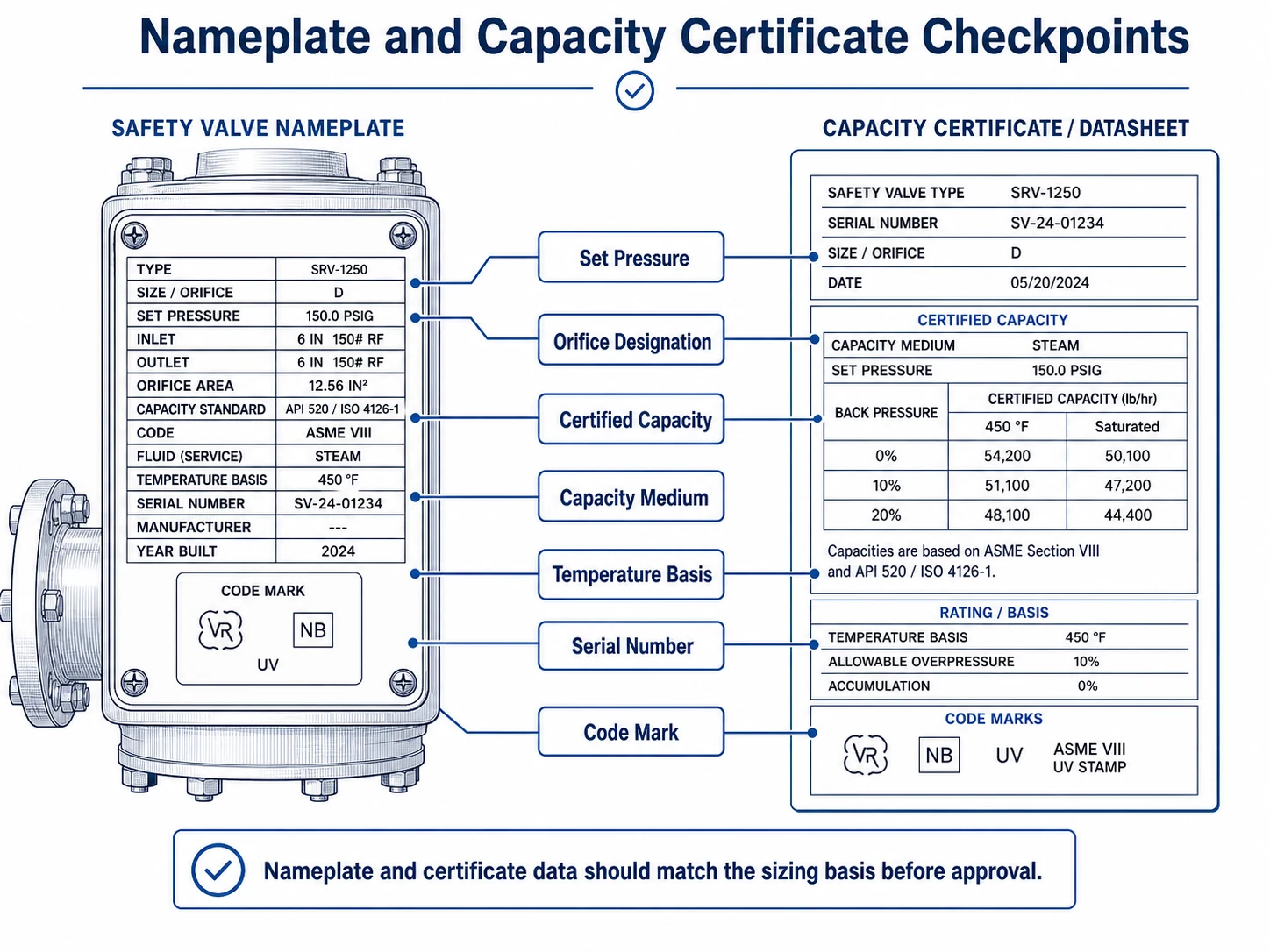
| Data to Check | Approval Purpose | Common Mismatch |
|---|---|---|
| Manufacturer, model and design | Links the physical valve to the certified device family. | Quotation model differs from certificate model. |
| Serial number or traceable identification | Connects the valve, nameplate and test records. | Generic certificate supplied without valve traceability. |
| 整定压力 | Confirms the required opening condition. | Certificate or nameplate pressure differs from approved datasheet. |
| Orifice designation and area | Connects the selected geometry to capacity. | Same body size offered with a smaller internal orifice. |
| 认证泄放能力 | Demonstrates capacity against the required load. | Supplier states “suitable” without a traceable capacity value. |
| Capacity medium and basis | Shows whether capacity is for air, steam, water or another condition. | Air value compared directly with process gas without conversion. |
| Pressure and temperature basis | Confirms that the capacity applies to the approved relieving condition. | Normal conditions used instead of relieving conditions. |
| 背压工况 | Confirms correction and valve-type suitability. | Certificate assumes atmospheric outlet while project uses a closed header. |
| Code or certification marking | Supports project compliance where required. | Marketing logo shown instead of the required certification basis. |
| Test and calibration reports | Confirms set pressure, pressure test and specified seat test. | Reports do not match the serial number or final set pressure. |
For a complete commercial and document package, use the 面向工程师和采购人员的安全阀采购检查清单.
When Sizing Requires Specialist Engineering or Manufacturer Review
The following conditions should not be reduced to a simple catalog comparison:
1
两相流或闪蒸流
Phase change can alter required area, reaction force and outlet-system behavior.
2
Reactive or Runaway Systems
Relief load can depend on kinetics, heat generation, gas generation and emergency response.
3
High-Viscosity Liquid
Viscosity correction may be iterative and linked to the selected orifice.
4
可变背压
Changing outlet pressure can affect capacity, opening and reseating.
5
Common Flare or Relief Header
Simultaneous events and network pressure require system-level analysis.
6
Multiple Relief Devices
Staggered set pressures and combined capacity must follow the governing code basis.
7
Rupture Disk Combination
Combination factors, pressure loss and fragmentation or leakage risks must be reviewed.
8
High Pressure or Extreme Temperature
Real-gas behavior, materials, correction factors and certified limits can control selection.
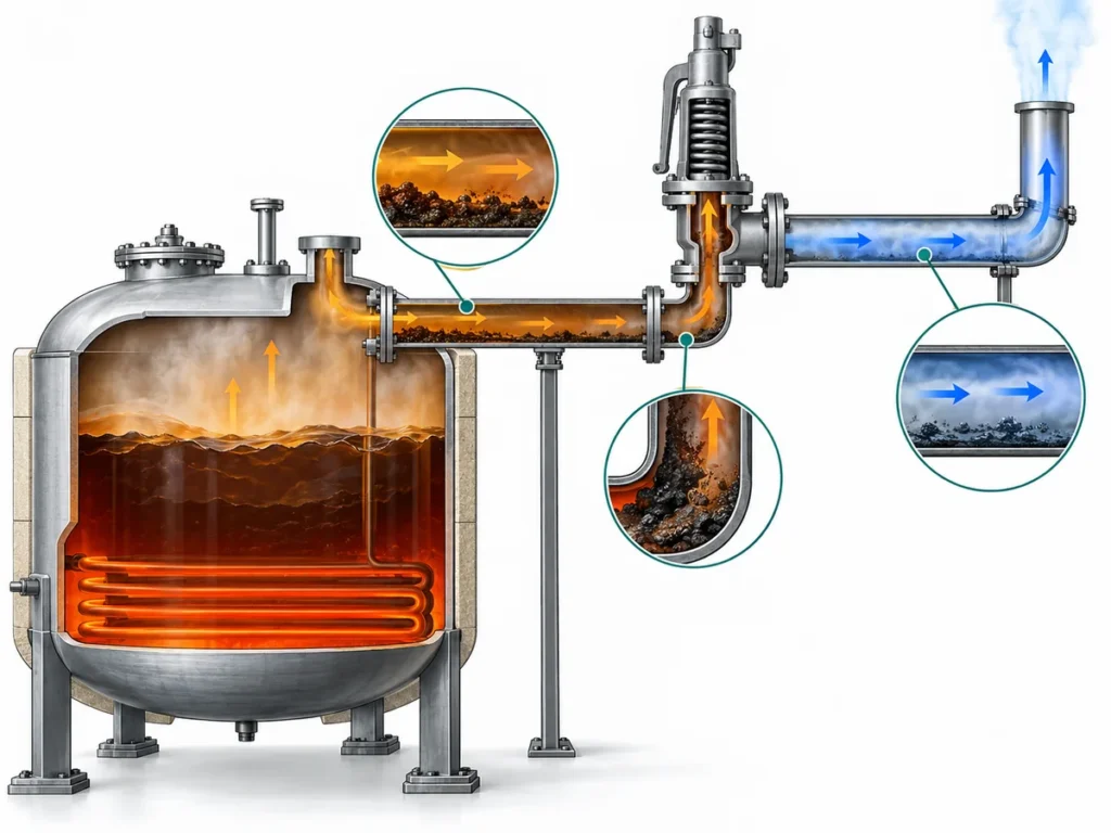
9
Dirty, Crystallizing or Polymerizing Media
Nominal capacity is irrelevant if the flow path or sensing system cannot remain functional.
Common Safety Valve Sizing Mistakes
- Selecting by inlet and outlet size. Mechanical fit does not prove orifice area or capacity.
- Using normal process flow as the relief load. The governing emergency case may be substantially different.
- Checking set pressure but not capacity. A valve can open correctly and still be unable to control the event.
- Using air capacity directly for another gas. Molecular weight, temperature, compressibility and pressure basis may require conversion.
- Ignoring flashing or two-phase flow. A single-phase equation may understate the required area or misrepresent discharge behavior.
- Ignoring back pressure. Closed headers, silencers and outlet piping can affect both calculated and installed suitability.
- Using an assumed discharge coefficient. The required coefficient must come from the approved calculation and certification basis.
- Adding an arbitrary safety factor. Excessive oversizing is not a substitute for correct relief-load analysis.
- Failing to recalculate after process changes. Increased throughput, changed composition, new heat input or modified discharge piping can invalidate the old basis.
- Accepting a generic certificate. Documents must be traceable to the offered device, orifice, pressure and capacity basis.
Safety Valve Sizing Checklist for Engineers and Buyers
| 步骤 | 审查项目 | 所需依据 | 状态 |
|---|---|---|---|
| 1 | Protected equipment identified | Tag, datasheet, drawing or P&ID | ☐ |
| 2 | MAWP and code basis confirmed | Equipment design documentation | ☐ |
| 3 | Set pressure and arrangement confirmed | Approved datasheet or calculation | ☐ |
| 4 | Credible relief scenarios listed | Relief study or engineering review | ☐ |
| 5 | Governing required capacity established | Calculation with units and revision | ☐ |
| 6 | Relieving pressure and temperature stated | Calculation input sheet | ☐ |
| 7 | Fluid properties and phase verified | Process data or property source | ☐ |
| 8 | Required discharge area calculated | Approved method or software output | ☐ |
| 9 | Selected orifice meets area requirement | Manufacturer or API 526 mapping | ☐ |
| 10 | Certified capacity meets required load | Traceable capacity data | ☐ |
| 11 | Back pressure and inlet loss reviewed | Piping calculation or engineering analysis | ☐ |
| 12 | Nameplate and certificates match | Final approved document package | ☐ |
| 13 | Management-of-change check completed | Current process and discharge configuration | ☐ |
Have a Sizing Sheet or Existing Valve Nameplate?
Send the equipment data, relief scenario, required capacity, relieving pressure and temperature, fluid properties, back pressure, existing valve nameplate and project standard for an engineering-oriented RFQ review.
Upload Datasheet for Review 获取安全阀报价FAQ About Safety Valve Sizing and Certified Capacity
如何为安全阀定径?
识别受保护设备及可信泄放工况,计算主导所需泄放量,确认泄放压力、温度及介质物性,计算所需泄放面积,选择合适的流道孔径,并核实在批准工况下的认证或制造商文件载明的排量。
什么是认证泄放能力?
认证排量是与特定泄压装置设计和认证基准相关的经核实的流量值,用于确定所选装置是否能为所需泄放负荷提供足够的排量。
安全阀的口径与连接尺寸相同吗?
不能。连接尺寸只描述进出口的机械接口。泄放能力取决于内部泄放面积、阀门结构、阀瓣升程、排放系数、泄放工况、修正系数及认证排量。
流道孔径尺寸与进口尺寸相同吗?
不。流道孔径或泄放面积是用于确定排量的内部流通面积。进口尺寸是与被保护设备的连接尺寸。进口尺寸相同的阀门可采用不同的流道孔径,并提供不同的排量。
为什么整定压力正确的安全阀仍可能出现选型偏小?
整定压力定义开启条件,并不定义阀门能够泄放的流量大小。阀门可以在所需压力下开启,但其认证排量仍可能小于主导泄放负荷。
安全阀应选择多大的额外排量?
所选定的验证排量必须满足经批准的核算基准下的所需载荷。并非每个项目都存在通用的附加百分比。任何余量均应遵循项目规范并经过责任工程师审查,同时应避免过度放大选型。
认证空气排量能否用于工艺气体?
未经复核不可直接使用。实际气体分子量、温度、压缩系数、压力基准及适用的计算方法可能需要换算或经制造商确认。
何时需要进行两相流安全阀选型计算?
当气体和液体可能同时流动,或液体在降压过程中可能显著闪蒸时,需要进行两相流校核。此类工况通常需要采用经过验证的专门计算方法,而不能仅使用单纯的气体或液体计算公式。
安全阀何时需要重新定径?
当处理量、工作压力、温度、组分、设备 MAWP、泄放工况、火灾基准、控制系统、进口管道、出口管道、火炬总管或其他排放系统条件发生变化后,应重新校核定径计算。
哪些文件可以证明安全阀的排量?
典型证据包括经批准的定径计算书、制造商数据表、孔径信息、经认证或有记录的排量数据、铭牌信息、规范或美国国家锅炉与压力容器检验师协会(National Board)认证信息、试验记录及技术批准文件。