Узнайте, как условия эксплуатации с хлором, материалы компонентов, изоляция разрывной мембраной, противодавление и отвод сброса влияют на выбор предохранительного клапана.

Предохранительные клапаны для хлорной среды не следует выбирать, просто останавливаясь на “коррозионностойком” материале корпуса. Фактическое состояние хлора, компоненты, которые могут контактировать со средой, схема сброса давления и место сброса — всё это влияет на итоговую спецификацию. Материал, приемлемый в одних условиях хлорной среды, может оказаться непригодным в других, а система улавливания сброса может создать противодавление или вторичное воздействие, которое необходимо учитывать вместе с клапаном, а не после него.
Таким образом, практическая последовательность выбора такова: определить хлорную среду, установить, какие части устройства сброса могут контактировать с этой средой, отобрать материалы по компонентам, оценить любую схему отключения как часть системы защиты от превышения давления, а затем проследить путь сброса до системы выпуска или улавливания. Окончательный выбор по-прежнему требует определения главенствующего сценария сброса, требуемой пропускной способности, данных изготовителя, применимого кода или стандарта и специфических требований проекта по приёмке.
Предохранительные клапаны для хлорной среды: сначала определите условия
“Хлорная среда” — слишком широкое понятие, чтобы служить спецификацией материала. Прежде чем сравнивать материалы или конфигурации клапанов, инженеру необходимо знать, в каком состоянии хлор может фактически воздействовать на устройство при нормальной работе и при сбросе.
Первое различие — фазовое состояние. Газообразный или парообразный хлор, жидкий хлор, а также любые возможные смешанные или изменяющиеся состояния не влекут автоматически одинаковых требований к материалу или расчёту. Второе — влажность. Сухой и влажный хлор нельзя рассматривать как взаимозаменяемые среды. Современные рекомендации по безопасности в хлорно-щелочной промышленности делают это различие особенно важным: материалы, приемлемые в контролируемых условиях сухого хлора, могут стать неприемлемыми при появлении влаги, тогда как другой материал может представлять серьёзную опасность в сухом хлоре, хотя ведёт себя иначе во влажных условиях.
Этот контраст полезнее универсальной таблицы материалов, поскольку объясняет, почему условия эксплуатации должны быть определены в первую очередь. Например, руководство CCPS предостерегает от отношения к углеродистой стали и титану так, будто их поведение можно без изменений переносить из сухой хлорной среды во влажную и наоборот. Инженерный вывод не в том, что один материал универсально “хорош”, а другой универсально “плох”. Он в том, что совместимость с хлором относится к определённому сочетанию состояния среды, температуры, материала, контакта компонентов и требований проекта.
Влажность также не следует сводить к единому универсальному порогу в ppm для всех хлорных систем. Приемлемое состояние зависит от соответствующего процесса, давления, температуры, объёма оборудования и действующей спецификации. Если проект устанавливает предел влажности для сухого хлора, этот предел должен быть перенесён в спецификацию клапана. Если нет, инженер не должен придумывать его на основе общей статьи или примера из несвязанного трубопровода.
Температура важна по той же причине. Нормальная рабочая температура может не совпадать с температурой при сбросе, а последняя может влиять как на пригодность материала, так и на расчёт сброса давления. Загрязнители или унос технологической среды также могут изменить воздействие по сравнению с тем, что подразумевает простая маркировка “хлор”.
Поэтому до начала выбора материала определение среды должно, в зависимости от применимости, устанавливать:
- защищаемое оборудование и главенствующий сценарий сброса;
- находится ли хлор в газообразном, парообразном, жидком состоянии или может менять состояние при сбросе;
- применимое состояние влажности и любую проектную спецификацию по влажности;
- соответствующие примеси или загрязнители;
- рабочая температура и температура при сбросе;
- рабочее давление, расчетное давление или MAWP и давление настройки;
- а также любые условия вниз по потоку, которые могут подвергнуть клапан воздействию среды, отличной от среды со стороны процесса.
Эта информация сама по себе не определяет выбор клапана. Она описывает условия, применительно к которым клапан может быть оценен.
Оценивайте материалы по воздействию на компоненты, а не только по материалу корпуса
Когда условия для хлора определены, следующий вопрос — не просто “Какой материал корпуса нам использовать?” Более полезный вопрос: Какие компоненты действительно контактируют с хлором, в каких условиях и как долго?
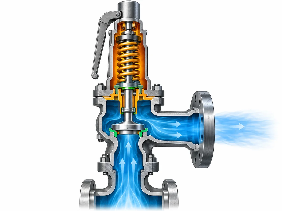
A safety valve is a system of pressure-retaining, moving, guiding, sealing, and spring-loaded components. Depending on the design, these parts may not share the same exposure. The body and nozzle may be process-wetted continuously. The disc and guide may be exposed differently during normal service and during opening. A bellows, spring, spindle, gasket, soft seat, O-ring, or other seal may have its own exposure path and material limitation.
That is why whole-valve suitability cannot be established by approving the body grade alone.
Separate metallic and nonmetallic decisions
Metallic compatibility and nonmetallic compatibility should be reviewed separately. A metallic body and trim combination that is acceptable for the defined chlorine condition does not prove that a soft seat, elastomer, gasket, or seal is equally suitable. Conversely, a gasket listed for one chlorine condition does not certify an entire valve assembly.
For each relevant component, the engineering review should identify:
- whether the component is continuously process-wetted, intermittently exposed, exposed only during relief, or isolated from the process under normal conditions;
- the chlorine state and temperature at that exposure;
- whether moisture or contaminants can change the corrosion environment;
- the exact material grade or compound proposed;
- the manufacturer or project evidence supporting that material in the defined condition; and
- any temperature, pressure, aging, maintenance, or inspection limitation that remains.
For springs and bellows, exposure deserves particular care because it is design-dependent. It is unsafe to assume that every spring is isolated from the process or that every bellows sees exactly the same environment as the valve inlet. Bonnet arrangement, venting, internal leakage paths, and the specific valve design determine what must be reviewed.
The same discipline applies to material equivalence. A similar grade name, approximate chemistry, or cross-standard correspondence is not enough to prove equivalent chlorine performance or project acceptance. If the project requires a particular material specification, heat condition, certification, or traceability level, the exact requirement should remain attached to the purchase specification.
The useful output from this step is therefore not a generic “best materials for chlorine” list. It is a component-exposure map that lets the engineer ask the correct compatibility question for each part of the valve.
Evaluate Whether the Safety Valve Needs Process Isolation
In some corrosive services, an upstream rupture disc can be considered to reduce normal exposure of the pressure relief valve to the process medium. For chlorine service, that can be a useful engineering option—but it is not an automatic requirement and should not be treated as a corrosion shortcut.
Adding a rupture disc changes the protection system. The disc and valve are no longer independent devices that can simply be selected separately and installed in series.
A combination arrangement introduces at least three additional questions.
First, the relieving capacity must be verified for the combination. The standalone capacity of the valve should not automatically be assumed to remain the certified or documented capacity of the assembled rupture-disc/PRV system. The applicable code basis and manufacturer data need to support the combination being used.
Second, the space between the rupture disc and the valve matters. If pressure accumulates in that interspace, it changes the differential pressure acting across the rupture disc and can therefore change its behavior. The arrangement may require venting, pressure indication, monitoring, or another approved method of detecting pressure in that cavity. The exact method depends on the device design, code basis, and project specification.
Third, isolation changes the exposure pattern rather than eliminating the material problem. Under normal operation, the rupture disc may reduce direct contact between the process and the relief valve. During a relief event, after disc opening, or if leakage occurs, the PRV can still be exposed to chlorine. The rupture disc itself, its holder, gaskets, the interspace connection, and the downstream valve components still require appropriate materials.
This creates a real engineering trade-off. Isolation can reduce normal corrosive exposure of the valve, but it adds another pressure-relief device, another material interface, another capacity relationship, and additional inspection and monitoring responsibilities.
Does the defined process and maintenance strategy justify isolating the PRV, and can the disc-and-valve combination be verified as a complete pressure-protection system?
If the answer is yes, the RFQ should identify the proposed combination arrangement and require the manufacturer or engineering authority to confirm the capacity basis, material compatibility, interspace treatment, pressure relationships, installation details, and applicable code requirements.
Design the Discharge Path as Part of the Valve Specification
A chlorine-service relief device cannot be specified responsibly without knowing where the discharge goes.
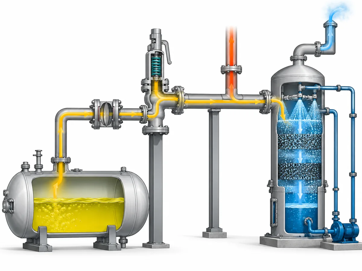
Depending on the facility and governing requirements, relieved chlorine may be routed to a closed receiver, treatment system, scrubber, common relief header, or another approved destination. The correct destination is project- and jurisdiction-specific. This article does not establish that every chlorine relief must discharge to a scrubber, nor does it establish that atmospheric discharge is acceptable for a particular installation.
The engineering point is that the discharge destination can feed back into the valve decision.
Containment can create back pressure
A relief valve discharging into a closed system may see наложенное противодавление before it opens and возникающее противодавление as relief flow passes through the outlet piping, header, receiver, or treatment equipment.
Those pressures can affect valve operation, available relieving capacity, stability, and configuration selection. The magnitude and variability of back pressure therefore need to be evaluated against the selected valve’s documented limits. Simply specifying a balanced bellows or pilot-operated design does not make every back-pressure problem disappear; those configurations also have application limits that must be confirmed against manufacturer data and the actual system.
The discharge system should be evaluated as a flow path rather than a destination label. Relevant questions include:
- What pressure already exists at the valve outlet before relief begins?
- How much additional pressure can be generated while the required relief flow passes through the outlet system?
- Does the discharge header serve other relief devices that can operate simultaneously?
- Can liquid collect in the outlet piping?
- Is drainage required?
- Are reaction loads and pipe supports addressed?
- Can downstream vapor, condensate, liquid, or contamination reach the valve under credible operating conditions?
The last question is especially important in chlorine service because moisture can materially change corrosion behavior. That does предписывает mean that every closed relief header will introduce moisture into the valve. It means that if the actual piping arrangement makes downstream exposure or backflow credible, that exposure belongs in the material review.
Containment and material selection are connected
Consider a representative engineering scenario. A process system contains chlorine under a controlled dry condition, while the relief outlet connects to a treatment system. The valve body material might initially be screened against the process-side dry condition. But if the downstream arrangement can subject outlet-side components to a different vapor condition, condensation, liquid accumulation, or back pressure, the engineer has two distinct environments to consider.
That scenario is illustrative, not a recorded project. Its value is the decision logic: material suitability must follow actual exposure paths, and those paths do not necessarily stop at the valve inlet.
The same reasoning applies when a rupture disc is installed upstream. Normal process exposure may be reduced, but relief-event exposure and downstream conditions still need to be considered. The pressure-protection system must work as a whole—from protected equipment, through any isolation device and relief valve, into the disposal or containment system.
Build the Chlorine-Service Verification Package Before RFQ
An RFQ that says only “Need a chlorine-compatible safety valve” leaves the most important engineering questions unanswered.
A supplier cannot safely establish material suitability, configuration, capacity, or documentation requirements from the medium name and connection size alone. Connection size is not relieving capacity, set pressure is not relieving capacity, and a material description is not a sizing basis.
A useful chlorine-service RFQ should provide enough information to evaluate both the service-compatibility problem и pressure-relief problem.
| Input to provide | Почему это меняет решение |
|---|---|
| Защищаемое оборудование и управляющий сценарий сброса | Establishes what event the valve must protect against and forms the basis for required relieving load. |
| Chlorine phase and process composition | Affects both sizing and material exposure. |
| Moisture condition or project dry-chlorine specification | Can materially change corrosion and compatibility decisions. |
| Operating pressure and design pressure/MAWP | Establishes the pressure relationship surrounding the set point and normal operating margin. |
| Давление настройки | Defines the valve’s opening pressure basis but does not establish capacity. |
| Требуемая производительность сброса и основа расчета | Provides the load the selected device or device combination must be able to relieve. |
| Рабочая и температура сброса | Influences material suitability and the relieving calculation. |
| Наложенное и нарастающее противодавление | Can affect valve configuration, capacity and stability. |
| Схема входного и выходного трубопровода | Identifies pressure-loss, support, discharge and exposure issues that cannot be seen from the valve datasheet alone. |
| Proposed rupture disc or isolation arrangement, if any | Triggers combination-capacity, material, monitoring and installation review. |
| Required body, trim, seat, seal, gasket, spring or bellows materials | Allows component-level compatibility review instead of body-grade-only selection. |
| Discharge destination or containment concept | Establishes the downstream conditions the relief device must operate against. |
| Applicable code, jurisdiction and project specification | Defines the actual acceptance basis; a standard name should not be assumed from the service alone. |
| Required inspection, material and test documentation | Establishes traceability and acceptance deliverables before quotation or order. |
Where an existing valve is being replaced, the old nameplate and connection dimensions can help identify the existing device, but they do not establish a safe direct replacement. Capacity basis, materials, service condition, back pressure, configuration, documentation, and project requirements still need to be checked.
The same caution applies to catalog data. A manufacturer’s general material matrix can identify available construction options, but it should not be converted automatically into a chlorine-suitability statement. Exact suitability belongs to the selected product configuration and the defined service condition.
Before requesting a final valve selection, assemble the chlorine condition, relief scenario, required capacity, pressure and temperature basis, back pressure, material requirements, any rupture-disc arrangement, discharge destination, and documentation requirements. With those inputs available, an engineering review can determine which product configuration and material set should be evaluated against the actual project.
Ask a Safety Valve Engineer: send the operating and relieving conditions, required relieving capacity or calculation basis, chlorine condition, discharge arrangement, back pressure, proposed materials, applicable project requirements, and any existing valve or rupture-disc data. The review should confirm suitability and capacity from the selected product data rather than assuming them from a generic chlorine-service description.