Узнайте, когда отсечённая жидкость создаёт сценарий сброса при тепловом расширении, что определяет пропускную способность и давление настройки, и какие данные необходимо проверить перед выбором клапана.

Заблокированная по жидкости линия может стать проблемой избыточного давления, когда жидкость оказывается запертой внутри замкнутого контура давления и её температура может повышаться без достаточного свободного объёма или другого подходящего пути для компенсации расширения. Поэтому первый инженерный вопрос — не “Какой предохранительный клапан для теплового расширения мне купить?” а “Действительно ли на этом участке возникает достоверный сценарий сброса давления при тепловом расширении?”
Закрытая арматура сама по себе не создаёт полный сценарий сброса давления. Диаметр трубопровода не определяет требуемую пропускную способность. Нормальный режим работы с жидкостью не доказывает, что среда остаётся однофазной при прохождении через устройство сброса давления. Даже правильно подобранный клапан необходимо проверять с учётом его сбросной линии и ожидаемого противодавления.
Определить замкнутый контур → подтвердить сценарий теплового расширения → установить требуемую пропускную способность → задать базис давления → проверить состояние сбрасываемой среды → проверить выходную систему → оценить вариант клапана и обоснование для запроса предложения.
Руководство UK HSE по технологическим трубопроводам признаёт, что жидкость может быть заперта между закрытой арматурой и что изменения температуры могут затем вызывать тепловое расширение и потерю герметичности. Оно также рассматривает сброс давления исходя из фактических рабочих условий и условий изоляции, а не только из наличия клапана. Руководство HSE по трубопроводам.
Для более широкого контекста избыточного давления в трубопроводах см. руководство ZOBAI по применению сброса давления в трубопроводах. На этой странице рассматриваются несколько сценариев избыточного давления в трубопроводах; данная статья посвящена только тепловому расширению запертой жидкости.
Когда заблокированная по жидкости линия становится случаем избыточного давления при тепловом расширении?
Сценарий теплового расширения начинается с реальной границы замкнутого объема жидкости под давлением,,
а не просто с низкого расхода или одного закрытого клапана.
-
Определите границу изоляции.
Определите клапаны, технологические присоединения оборудования или другие точки изоляции, которые могут удерживать жидкость. -
Определите, что находится в замкнутом объеме.
Установите, может ли участок стать полностью заполненным жидкостью или иным образом достаточно ограниченным,
чтобы тепловое расширение имело значение. -
Определите реальное повышение температуры.
Учтите соответствующие рабочие, остановочные, резервные или внешние условия, которые могут нагреть
замкнутую жидкость. -
Сопоставьте сценарий с защищаемой границей давления.
Определите, может ли возникшее состояние создать нагрузку на применимую основу давления для
трубопровода или оборудования.
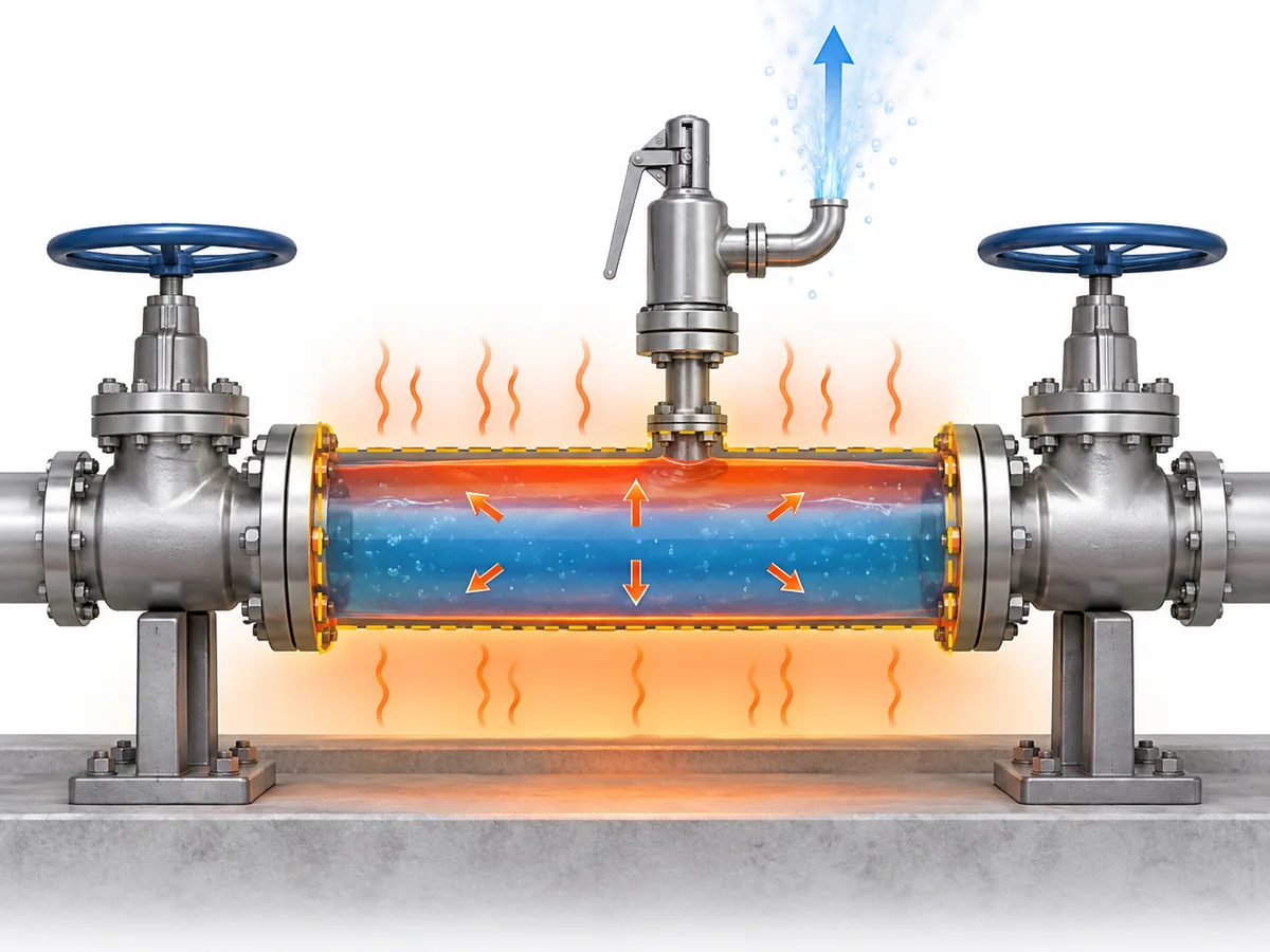
Жидкости значительно менее сжимаемы, чем газы. Когда изолированный объём в значительной степени
заполнен жидкостью, дополнительный объём жидкости, образовавшийся при нагреве, может привести к
резкому повышению давления, если система не располагает достаточным способом его компенсации или сброса.
Подвод тепла зависит от конкретной установки. В зависимости от системы соответствующие источники могут включать
нагрев от окружающей среды или солнечной радиации, обогрев трубопровода, нагретую окружающую зону или соседнее технологическое
оборудование. Наличие одного из этих источников не делает его автоматически определяющим
случаем; достоверное состояние должно быть установлено для фактической установки.
Отключённый участок не означает просто “отсутствие потока”.”
Это означает, что система может создать замкнутую границу давления жидкости в условиях,
когда тепловое расширение может создать нагрузку на эту границу.
Это условие, которое необходимо установить до расчета или выбора устройства сброса давления.
Нужен ли каждой отсеченной жидкостной секции отдельный терморегулирующий предохранительный клапан?
Не автоматически.
Выявление достоверного сценария теплового расширения подтверждает, что риск превышения давления
требует адекватного инженерного решения. Это само по себе не доказывает, что
единственно приемлемым решением является одна конкретная схема с отдельным терморегулирующим предохранительным клапаном.
| Инженерный вопрос | Что фактически установлено? |
|---|---|
| Может ли жидкость оказаться запертой и нагреться? | Существует потенциальный сценарий теплового расширения. |
| Может ли это условие создать нагрузку на защищаемую границу давления? | Необходимо оценить защиту от превышения давления. |
| Обязательно ли решение должно быть отдельным терморегулирующим предохранительным клапаном? | Это зависит от принятой стратегии защиты и проектных условий. |
| Подходит ли конкретный клапан? | Для этого требуется определённый режим работы и подтверждение по конкретному изделию. |
Depending on the system and applicable engineering basis, protection can involve a
pressure-relief device or another engineered arrangement that prevents unacceptable
pressure from developing. A solution accepted for one service or jurisdiction should
not be generalized to every process line.
API Standard 521 is a system-level pressure-relief and depressuring reference for petroleum,
petrochemical, LNG and related facilities. Its scope supports evaluating the relief scenario
and system before treating a product name as the design decision.
API Standard 521 information.
The terminology can also mislead procurement. Hydrostatic relief valve
is used in some industries for devices protecting piping where liquid can be trapped
between shut-off valves. That practical terminology overlap does not make
“hydrostatic relief valve” and “thermal relief valve” universally interchangeable across
every fluid, code or industry.
Scenario confirmed → protection strategy defined → applicable project/code basis checked
→ device selected and verified.
For broader standards context, see
ZOBAI’s API 521 pressure-relief systems guide
.
What Determines the Required Thermal Relief Rate and Valve Capacity?
A thermal expansion relief valve should be selected from the
required relieving duty, not from pipe diameter or a habitual
“small thermal valve” size.
For a liquid-filled thermal-expansion case, the relief requirement depends on the thermal
condition and on fluid properties that determine how the liquid responds as temperature
changes. Once the required relieving flow is established, actual valve sizing also depends
on the applicable relieving pressure, temperature, outlet/back-pressure condition and
fluid state.
Credible thermal condition → applicable fluid properties → required relieving rate
→ relieving pressure and outlet conditions → applicable sizing method
→ required flow area/capacity → candidate valve capacity verification.
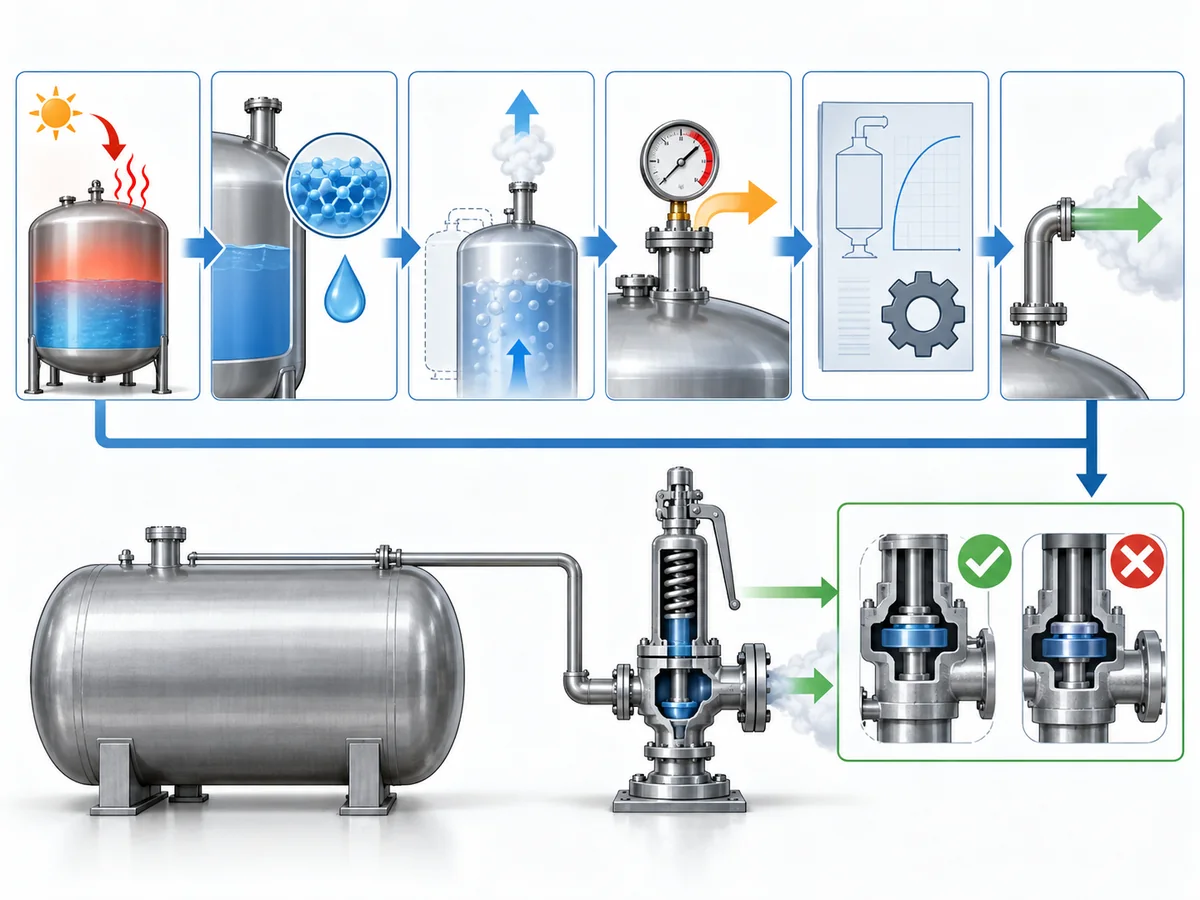
Two shortcuts are worth rejecting. Размер соединения — это не производительность:
a valve may fit the line mechanically while still lacking the capacity required for the
relief case. And “thermal relief flow is often relatively small” is not a sizing
метод: even a modest duty has to be established before a candidate valve can
be accepted.
API 520 Part I is specifically concerned with pressure-relieving-device sizing and
selection within its scope.
API 520 Part I information.
For the detailed general sizing workflow rather than repeating it here, see
ZOBAI’s safety valve sizing and certified relieving capacity guide
.
The practical inputs for this thermal-expansion case include:
- the protected section and relevant trapped volume;
- the credible thermal condition or heat input;
- fluid identity and the physical properties required by the applicable calculation;
- давление сброса и температура;
- the required relieving rate;
- expected back pressure; and
- the fluid-state assumption used by the sizing method.
Only after the required duty has been established should the selected valve’s documented
capacity be compared against it.
Thermal relief is duty-sized, not simply small-sized.
How Should the Set-Pressure Basis Be Established?
Set pressure should be derived from the pressure boundary being protected,
not copied from normal operating pressure or selected from a generic percentage rule.
That separation is consistent with recognized relief-device specification practice:
operating pressure, set pressure, relieving/design temperatures, allowable overpressure,
back pressure and required capacity are treated as distinct inputs rather than
interchangeable values.
Baker Hughes pressure-relief valve specification guidance
.
| Термин давления | Role in the thermal-relief decision |
|---|---|
| Рабочее давление | The pressure the system normally experiences. |
| Protected design / allowable pressure basis | The applicable pressure boundary for the piping or equipment being protected. |
| Давление настройки | The specified pressure associated with the relief device beginning its defined opening action. |
| Давление сброса | The pressure condition used for relief sizing or capacity assessment. |
| Противодавление | Pressure acting on or downstream of the valve outlet. |
Those values are related, but they are not interchangeable. Identify which piping and
components lie inside the blocked-in boundary, then establish the governing pressure basis
under the applicable design code, equipment rules and project specification before
assigning the valve set pressure.
Scope discipline matters here. A pressure rule written for a vessel should not automatically
be transplanted into generic process piping, and a regulation written specifically for LPG,
ammonia or another service should not be generalized to unrelated fluids or jurisdictions.
This article therefore does not create a universal rule such as
“set the thermal relief valve at a fixed percentage above operating pressure.”
Where a numerical relationship is prescribed, it belongs to the applicable equipment,
code, project and jurisdictional basis.
For an RFQ, set pressure should be treated as the result of a protected-system engineering
decision, not merely as a field to complete on a vendor datasheet.
Why the Relieving Fluid State Must Be Checked, Not Assumed
A line can be liquid-filled before the relief event without remaining a simple
single-phase liquid system throughout the complete relieving path.
Relief-valve engineering guidance distinguishes straightforward liquid sizing from cases
in which subcooled liquid can flash as pressure falls through the valve. That makes the
relieving-state check a real sizing boundary rather than a semantic detail.
LESER engineering guidance.
As pressure changes through the valve and downstream piping, the relationship between fluid
pressure and temperature can change. Under some conditions, the liquid remains adequately
subcooled and a liquid-sizing basis remains appropriate. Under others, flashing or a more
complex phase condition may need to be considered.
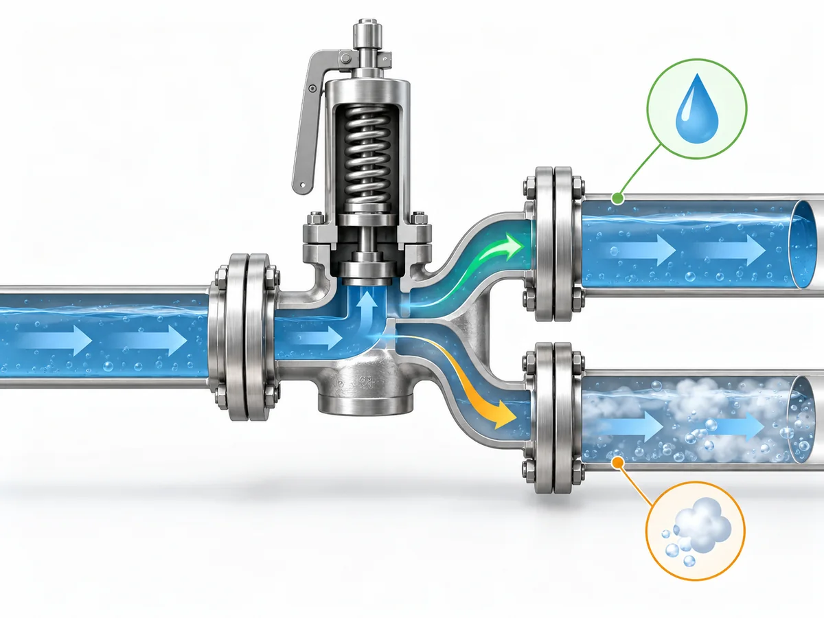
At the relevant relieving pressure and temperature—and as pressure falls through the
valve and outlet system—does the fluid remain in the phase assumed by the sizing method?
If the assumed phase remains valid, the case can continue under the appropriate liquid-sizing
methodology. If meaningful phase change occurs, the required inputs and sizing treatment can
change. That does not mean every thermal-expansion case is two-phase; it means the phase
assumption should be verified rather than inherited from the normal operating description.
A procurement description such as “liquid service, thermal relief”
therefore does not by itself prove the relieving-state assumption required for final sizing.
This article treats initial phase и relieving phase
as related but separate engineering inputs.
Why Discharge Routing and Back Pressure Are Part of the Relief Decision
A correctly selected valve is not enough if the installed relief path cannot perform
under the defined scenario.
Protected section → valve inlet → relief device → outlet piping → disposal or recovery destination.
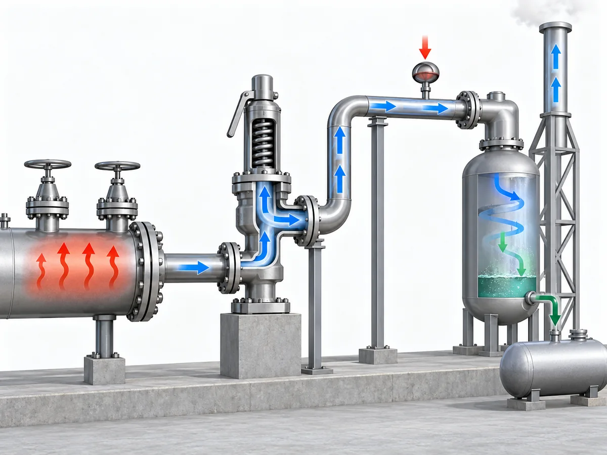
The review should establish where the relieved liquid will go, whether that route remains
available during the relief case, and what pressure the downstream system will impose on
the valve.
Back pressure can influence relief-valve behavior and available capacity, depending on the
valve design and system. Emerson’s pressure-relief-valve engineering handbook treats back
pressure as a factor that can affect opening or reseating behavior, stability and capacity,
so it belongs in candidate verification rather than being left as a post-purchase piping detail.
Emerson Pressure Relief Valve Engineering Handbook
.
For a deeper treatment of that interface, see
ZOBAI’s back-pressure and bellows engineering guide
.
The destination itself is service-dependent. A small expected thermal-relief rate does
not prove that unrestricted atmospheric discharge is acceptable. Conversely, a closed
return, drain or recovery system is not automatically suitable if it imposes unacceptable
back pressure or can be isolated when relief is required.
ISO 23251 provides an international pressure-relief-system framework for petroleum,
petrochemical and natural-gas industries. Its current 2019 edition explicitly supplements
API 521 6th Edition, so project teams should confirm the adopted standard set rather than
silently treating different editions as textually equivalent.
ISO 23251 information.
Where can the relieved fluid go without compromising either safe disposal or the valve’s
ability to perform its relief function?
Detailed flare design, closed-header hydraulics and valve-architecture thresholds belong
to separate engineering work. This article only needs to establish that the outlet system
forms part of the relief decision.
What Information Belongs in a Thermal-Relief RFQ or Engineering Review?
A technically useful RFQ should describe the protected system and relief duty,
not simply request a valve by nominal size.
Separate the process inputs from the supplier verification:
| Buyer / engineer should define or assign | Supplier / candidate should confirm |
|---|---|
| Protected piping or equipment boundary | Exact valve configuration offered |
| Fluid and relevant composition | Wetted-material, seat and seal suitability |
| Normal fluid state | Pressure-temperature suitability |
| Рабочее давление и температура | Available set-pressure capability |
| Governing protected-pressure basis | Documented capacity for the specified duty |
| Credible thermal condition or heat source | Selected flow area or valve size |
| Required relieving rate, or responsibility for determining it | Effect of specified back pressure on the candidate |
| Relieving-phase assumption | Connection and pressure-class suitability |
| Ожидаемое противодавление | Applicable inspection or test documentation |
| Relief destination | Requested conformity documentation, where applicable |
| Applicable project code or specification | Deviations, limitations and unresolved points |
Required relieving capacity is not the same as connection size.
One is a process-protection requirement; the other is primarily an installation characteristic.
Required capacity is also not the same as compliance evidence.
Capacity documentation addresses the flow-performance question under the applicable basis.
Material certificates, inspection records or other project-required conformity evidence
answer different procurement questions.
A supplier should not have to guess the relief scenario. If the protected pressure basis,
thermal condition, required relieving rate, fluid state or expected back pressure remains
undefined, those gaps should be resolved before a proposed valve is treated as an approved
candidate.
Can the proposed valve be traced back to a defined thermal-expansion duty, protected
pressure boundary, relieving state and outlet condition—and does the supplier evidence
address each of those requirements?
If not, the candidate is not ready for approval merely because a catalogue uses the words
термический сброс или hydrostatic relief.