了解安全阀出口反作用力、开式与闭式排放、管道载荷路径、支架与接管载荷,以及应力校核所需的输入条件。.

安全阀排放反作用力是泄放过程中由流体流动产生的机械载荷。它是排放管道设计的重要输入参数,但它 不自动等同于管道支架载荷、阀门接口载荷或相连设备管口载荷.
工程流程更为完整:
确定泄放工况 → 确定排放边界 → 计算相应的反作用力 → 追踪实际管道载荷路径 → 校核支架、管口载荷及所需的应力或动态分析。.
常见的失效点并不在于反作用力计算本身,而在于后续环节:反作用力按某一边界计算后,却被直接施加到实际安装管道上,仿佛它已经是最终的支架载荷或管口载荷。.
安全阀出口反作用力究竟代表什么?
当泄放介质离开安全阀或其排放系统时,,
排放边界处流体动量与压力的变化可能
产生机械反作用力。在敞开式可压缩介质排放中,常用
工程方法会同时考虑动量效应与压力推力
效应。该处理方法记录于
Emerson 泄压阀工程手册.
关键边界在于该计算结果所反映的内容。
排放反作用力 是相关联的载荷输入
与泄放流量相关。其本身并不确定:
- 特定管道支架处的反作用力;;
- 传递至阀门连接处的力或力矩;;
- 该阀门连接处的允许载荷;;
- 容器、集管或设备接管上的载荷;或
- 排放管道的组合应力状态。.
这些量取决于已安装管道的几何形状及其
约束条件。因此,诸如“阀门产生 X 力,所以
最近的支撑必须承受 X”这样的说法是不完整的。计算所得的
反作用力必须纳入真实装置的力学模型中,
才能判断排放管道在支撑和管口载荷方面的受力情况。.
关于更全面的入口、排液、安装方位及排放管路布置
要求,请参见
安全阀安装指南
.
本页重点讨论反作用力及其力学
解读。.
哪些输入参数决定出口反作用力?
不要从安全阀公称出口尺寸入手,而应从
泄放工况和实际排放条件入手.
不同流体状态需要采用不同的工程处理方法。.
Emerson 泄压阀工程手册针对气体或蒸汽、蒸汽、非闪蒸液体及两相流
分别给出了不同的计算方法
流量,而非一个通用的反作用力方程。.
| 输入 | 重要性 |
|---|---|
| 泄放质量流量 | 决定排放相关的动量。. |
| 流体与相态 |
确定适用的计算方法和假设条件。 适用。. |
| 泄放温度或排放温度 | 进入相应的热力学处理。. |
| 相关流体物性 |
气体/蒸汽、液体和两相方法需要不同的 属性。. |
| 出口或排放面积 |
定义用于力计算的排放边界的一部分。 计算。. |
| 出口压力 | 压力推力可能对反作用力产生影响。. |
| 环境压力或下游压力 | 定义排放所对应的压力边界。. |
| 敞开式或连通式排放布置 |
确定是否采用大气排放方式 适用。. |
| 实际下游几何结构 |
在将局部力转化为管道载荷问题时成为必要。 管道载荷问题。. |
实际含义很简单:两台出口相同的安全阀
如果各连接点的泄放流量、,
流体状态、压力边界或排放布置不同,其反作用载荷也会不同。.
相态假设需要特别注意。针对气体或
蒸汽建立的方法,不应仅因
连接尺寸相同就套用于液体排放。同样,假设
为非闪蒸工况的液体计算方法,并不自动适用于闪蒸液体,,
而均相两相模型仍以其所述
假设为条件。.
如果所需泄放量本身尚未确定,,
应先完成该项工作。
安全阀选型与认证泄放能力指南
负责该任务;本文将泄放流量视为
机械校核的输入条件。.
Why Open and Closed Discharge Systems Need Different Treatment
Before choosing a reaction-force calculation, determine
where the safety valve discharges.
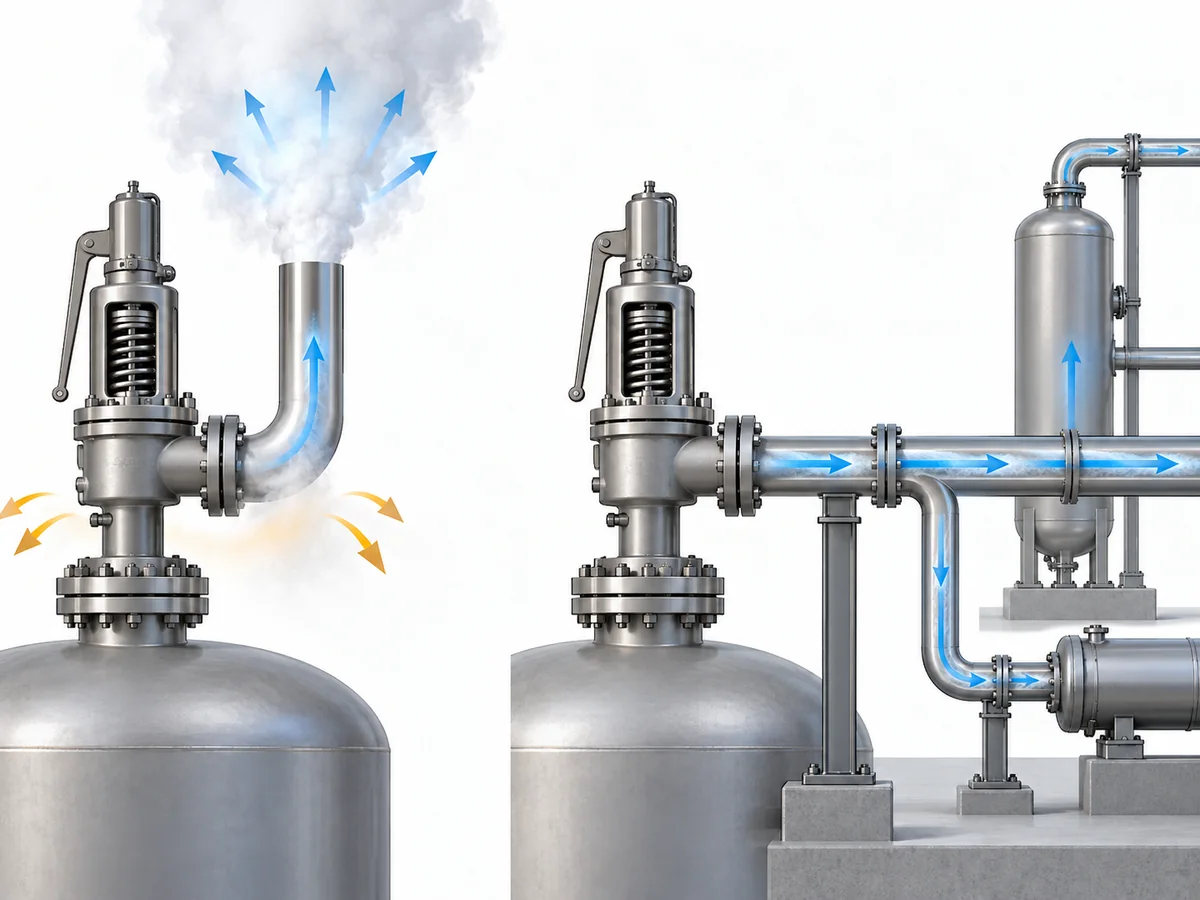
An open discharge releases fluid through a defined termination to
atmosphere. A closed discharge remains connected to downstream piping,
a header, or another disposal system. That difference changes the
calculation boundary.
API 520 第 II 部分
is the relevant API installation authority family, while manufacturer
engineering guidance such as the
LESER Engineering Handbook installation chapter
illustrates the open/closed-system distinction and its limitations.
| Open / atmospheric discharge | Closed / connected discharge |
|---|---|
| A terminal discharge boundary can usually be identified. | Downstream piping remains part of the pressure/flow system. |
| Open-discharge reaction methods may be applicable. |
An open-discharge formula should not be transplanted automatically. |
|
Momentum and pressure effects can be evaluated at the termination. |
Pressure, velocity, geometry, and transient behavior may interact through the connected system. |
| A local reaction vector can often be defined. |
System-level forces may depend on expansions, bends, restraints, and downstream conditions. |
Under an established steady-flow condition, forces within some closed
systems can partially balance. That does 不 justify
the blanket conclusion that a closed relief system has no mechanically
significant reaction load.
Changes in section, direction, downstream pressure, and transient flow
can still matter. The defensible rule is:
Define the discharge boundary before selecting the calculation method.
Back pressure belongs nearby in the engineering logic, but it is not
synonymous with reaction force. Back pressure describes the outlet
pressure condition affecting the relief system; reaction/support
analysis asks how the resulting fluid and pressure behavior loads the
mechanical system.
For detailed superimposed and built-up back-pressure discussion, use
the dedicated
背压与波纹管
指南。.
When Is a Steady Reaction Force Not Enough?
A steady-state reaction calculation answers a specific question:
what reaction is associated with the established relieving flow?
It does not necessarily answer:
what is the complete mechanical load history while the valve opens
and the discharge system responds?
During opening, pressure and flow change with time. A published study
on safety-valve blowdown by Muschelknautz and Wellenhofer reported
short-duration reaction-force peaks during the opening process in the
configurations they studied. That supports treating steady and transient
loading as related but distinct engineering questions rather than
assuming that one steady value describes the entire event.
See the
Wiley study on flow reaction forces during safety-valve blowdown.
A transient or dynamic review becomes more relevant when, for example:
-
the valve opening event is rapid compared with the response of the
piping system; -
pressure waves or unsteady flow in connected discharge piping may
affect the mechanical response; - the system is sensitive to short-duration loads; or
- the governing project/code basis requires a dynamic treatment.
This is a screening boundary, not a claim that every safety valve needs
a time-history analysis. The opposite shortcut is also unsafe: a single
steady-state force should not automatically be treated as the complete
event load.
The method must follow the piping code, edition, and project basis that
actually govern the installation.
ASME B31.1,
for example, is a Power Piping code and should not be treated as a
universal substitute for a different governing piping code. This
article therefore does not publish a universal dynamic load multiplier.
How Does Outlet Piping Geometry Change the Load Path?
Once the reaction force has been calculated, the next engineering
question is:
where does that load go in the installed piping?
Geometry controls much of that answer. Emerson Birkett technical
guidance notes that an unsupported discharge pipe can act as a lever,
so the mechanical load applied to the valve depends on both the
discharge reaction and the piping geometry. That is why pipe length,
direction changes, and restraint locations matter after the local
reaction force has been established.
See the
Emerson Birkett safety-relief-valve technical data.
Direction changes add another layer. At an elbow, the fluid momentum
changes direction, so the discharge system must be considered as a set
of force vectors, moment arms, supports, and boundary conditions rather
than as one scalar force traveling unchanged down the pipe.
Relieving flow → reaction vector → piping geometry → direction
changes and moment arms → restraints → valve/support/equipment loads.
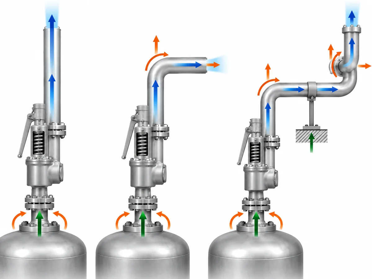
An offset, elbow, vent stack, silencer, reducer, or connection into
downstream piping can alter the load path. The exact consequence depends
on the actual geometry and restraints.
Supports also do more than carry weight. A guide, anchor, line stop, or
other restraint changes the mechanical boundary condition of the piping
system. Do not turn that into a fixed support-spacing rule: the suitable
arrangement depends on the actual piping geometry, restraint model, and
allowable loads.
The relief reaction is also only one load case. Depending on the
project, the installed system may have to accommodate dead weight,
thermal movement, pressure-related loading, discharge reaction, and
applicable transient or occasional loads.
A layout that works for weight does not automatically work for relief
loading. Conversely, adding excessive restraint simply to resist thrust
can create other mechanical consequences when the piping expands
thermally.
Why Reaction Force Is Not the Same as the Final Support or Nozzle Load
The reaction-force calculation and the final mechanical acceptance
check are separate engineering milestones.
| 数量 | What it represents | What controls it |
|---|---|---|
| Discharge reaction force | Flow-induced load associated with the relief event. |
Relief flow, phase/state, pressure boundary, outlet condition, and applicable calculation method. |
| Load at the valve connection | Force and moment transmitted between valve and connected piping. |
Reaction force, geometry, moment arms, restraints, and other piping loads. |
| Support reaction | Load carried by a particular support or restraint. |
Complete piping geometry, stiffness, restraints, and applicable load cases. |
| Equipment/nozzle load |
Load transferred to a vessel, header, or other equipment connection. |
Mechanical response of the connected system. |
| Pipe-stress result | Combined piping response. |
Pressure, weight, thermal, relief-event, and other project-defined load cases. |
The difference becomes clearer with a simple thought experiment.
Assume two systems have the same calculated discharge reaction. One has
a short, well-defined outlet route with a nearby engineered restraint.
The other has a longer offset before the piping is supported.
The flow reaction can be the same while the bending moment and loads
transmitted into the valve or supports are different.
This is why
allowable loads cannot be inferred from the reaction-force equation
.
A valve-nozzle allowable, vessel-nozzle allowable, support capacity, or
equipment allowable must come from the documentation applicable to the
actual valve, equipment, structure, or project.
Values from another manufacturer’s valve or another installation are
not substitutes. No model-specific ZOBAI allowable outlet/nozzle load
is established by this article, so none should be inferred from the
generic engineering discussion.
What Should Be Verified Before the Outlet Piping Support Arrangement Is Accepted?
The ten checks below are a practical engineering review
framework for this article. They are not presented as a
universal API or ASME mandated sequence. The governing project code,
equipment documentation, and piping/stress design basis remain the
authority for an actual installation.
-
Establish the relief duty.
Confirm the governing relief case and required relieving-flow basis.
If the required flow is still unknown, the mechanical reaction
calculation is premature. -
Establish the fluid and phase state.
Identify whether the relieving stream is gas/vapor, steam,
non-flashing liquid, or a case requiring two-phase treatment. -
Define the discharge boundary.
Confirm whether the valve discharges openly to atmosphere or into
connected downstream piping. For a connected system, also establish
the relevant downstream pressure and routing information. -
Use a reaction-force method that matches that boundary.
Keep the result tied to its calculation boundary instead of
immediately treating it as the load at a support. -
Map the real outlet geometry.
Record the valve outlet orientation, straight pipe lengths, elbows,
offsets, reducers or expansions where relevant, silencers or other
inline items where present, and connection to any vent, header, or
disposal system. -
Define the restraints.
Identify the actual supports, guides, anchors, line stops, structural
attachments, and other boundary conditions relevant to the piping
analysis. -
Include the other applicable load cases.
Determine which additional loads have to be considered under the
project’s design basis, including weight, thermal movement, pressure
effects, and any applicable occasional or dynamic case. -
Obtain the real allowable loads.
Use valve-, equipment-, support-, and project-specific documentation.
If a decision-critical nozzle or structural allowable is missing, the
mechanical acceptance is not complete. -
Decide whether the steady calculation is sufficient.
Confirm whether the installed configuration and governing design
basis require any additional transient or dynamic assessment. -
Close the piping/stress review.
For an actual project, the relief duty, calculation boundary, piping
layout, restraints, applicable load cases, and relevant allowable
loads need to be resolved before the mechanical acceptance can be
closed.
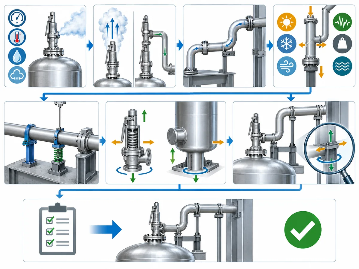
The useful project handoff is therefore not simply
“reaction force = ___.” It is:
relief duty + fluid state + discharge boundary + reaction-force basis
+ actual geometry + restraint model + applicable allowable loads +
dynamic-review status.
That package allows process/relief and piping/stress disciplines to work
from the same design basis.
Preparing a safety valve RFQ or outlet-system review?
Send the known relief case, fluid and phase, required relieving rate,
pressure and temperature conditions, back pressure or discharge route,
and applicable project requirements through
咨询安全阀工程师
.
ZOBAI can use confirmed valve/application inputs for the valve review;
final piping-support and stress acceptance remains dependent on the
installed project system.
A safety-valve reaction-force calculation is neither “just a formula” nor the final support design. It is the bridge between the relief calculation and the mechanical review of the installed discharge system.
Calculate the correct reaction for the correct discharge case, then verify how the actual piping carries it.