获取安全阀报价

请提供您的介质、整定压力、温度、口径、标准或数据表,我们的团队将审核您的需求并回复相应的后续步骤。.

弹簧式安全阀频跳:原因、诊断与纠正措施

Engineering troubleshooting guide Pipe support, inlet geometry and outlet routing are common review points after chattering is observed. Industrial engineering visual for article context; final layout should be confirmed by qualified engineering review. Controlled testing helps separate valve condition from system installation causes. Industrial engineering visual for article context; it does not replace a formal …

弹簧式安全阀颤振诊断:显示不稳定升程及校正检查要点.

Engineering troubleshooting guide

Technician checking pipe support near a spring-loaded safety valve after chattering diagnosis
Pipe support, inlet geometry and outlet routing are common review points after chattering is observed.

Industrial engineering visual for article context; final layout should be confirmed by qualified engineering review.

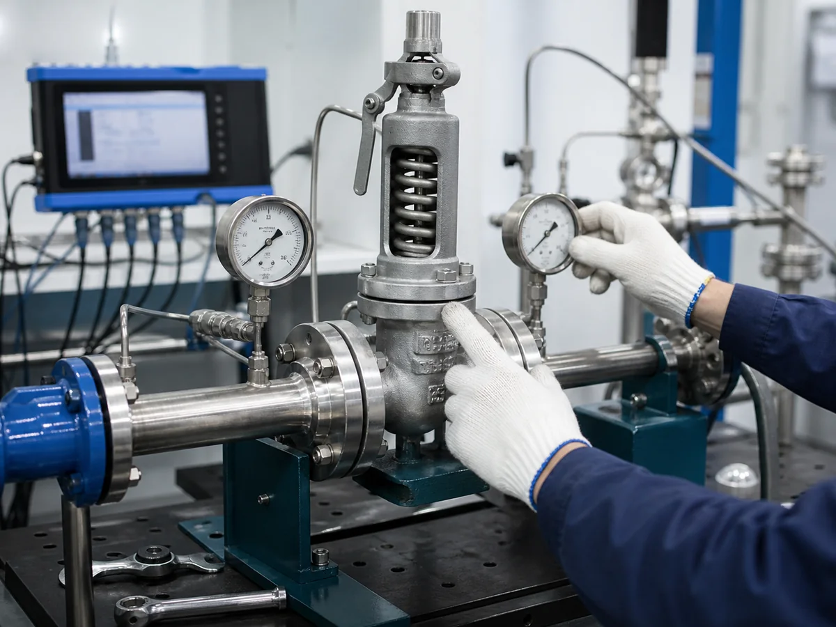
Spring-loaded safety valve diagnostic testing on a factory bench with pressure gauges
Controlled testing helps separate valve condition from system installation causes.

Industrial engineering visual for article context; it does not replace a formal test procedure.

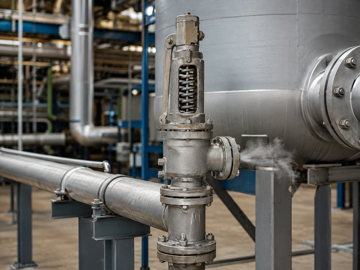
Plant engineer inspecting a spring-loaded safety valve installation for chattering diagnosis
Chattering diagnosis should start with the actual valve installation, inlet piping and outlet routing.

Industrial engineering visual for article context; final corrective actions should follow site review and applicable standards.

What Is Spring-Loaded Safety Valve Chattering, and What Should You Check First?

This guide addresses rapid, unstable cycling in an installed spring-loaded safety valve in which the disc repeatedly returns into seat contact. LESER summarizes the relevant ASME BPVC XIII/API 520 terminology, while EPSC independently describes chattering as rapid opening and closing. The page supports investigation of an installed valve event, not generic PRV dynamics or a product claim.

Quick answer
Chatter is a rapid, unstable valve-motion problem. Collect the event record, relief scenario, valve identity and inlet/outlet evidence; then correlate demand with model-level capacity, installation and valve condition. Keep the conclusion open when those inputs are missing, and route any correction through qualified engineering review.

Preserve the event before intervention: identify the protected equipment and relief scenario, record operating pressure and process changes, capture pressure/time trends where available, and document the valve nameplate, inlet branch, outlet route and recent modifications. Diagnosis should precede adjustment, replacement or piping change; a sound recording alone cannot establish the cause.

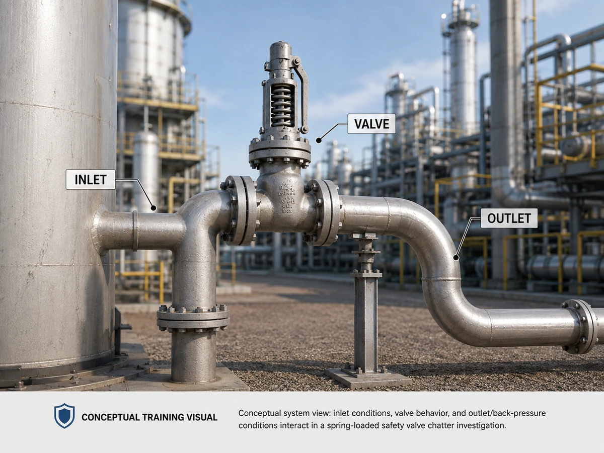
Installed spring-loaded safety valve in process piping in a conceptual unstable-relieving context
Conceptual training visual: an installed spring-loaded safety valve requires system-level evidence when unstable relieving behavior is suspected.

Conceptual engineering image; not a documented customer incident or measured field event.

Quick Recognition Questions

  • Did the event occur during a relief demand, near the opening region, or during repeated process pressure excursions?
  • Was the disc movement a stable opening followed by normal reseating, or repeated unstable motion?
  • Did the event begin after an inlet, outlet, process or valve change?
  • Which observations are measured, and which are only operator descriptions?

Evidence to Preserve Before Intervention

Preserve trend data, operator observations, video or vibration records where available, valve identification, configuration, installation photographs, recent work history and the relevant relief-case documentation. Avoid disturbing the installed evidence before the responsible engineering or inspection team defines the review method.

Before Troubleshooting, Confirm the Device and Relief Scenario

A chatter investigation starts with the protection basis, not with a spring adjustment. Plant documents may use safety valve, relief valve, safety relief valve, PSV, SRV or PRV differently, so first confirm that the installed device is the spring-loaded, reclosing pressure-relief device being investigated and identify its model, spring range, rated-capacity basis and applicable documentation.

Confirm what the valve protects

Identify the protected boiler, vessel, compressor discharge, exchanger, pipeline, tank system, reactor or skid, then identify the governing relief scenario. Required relieving load, fluid phase, relieving pressure and discharge behavior depend on that scenario.

Separate shop results from installed behavior

A valve can meet a shop set-pressure or leakage test and still be unstable in service because the test does not reproduce the installed inlet loss, outlet back pressure, sustainable process flow, process pulsation or piping loads. Conversely, poor as-found valve condition can contribute even when the piping is acceptable.

Engineering principle: chatter is a symptom of an installed valve-and-system event. The corrective path may be process stabilization, piping review, capacity review, controlled repair, valve reconfiguration or replacement; the evidence should determine which path applies.

Chatter vs Simmer, Flutter, Normal Reseating, Process Cycling and Seat Leakage

These terms should not be interchanged. The definitions below are limited to the technical references identified in the evidence ledger; the applicable valve documentation and project basis still govern a particular installation.

Observed behavior What it may indicate What it should not automatically be called Evidence to confirm Engineering next step
Rapid, unstable cycling that repeatedly brings the disc back into seat contact Chatter A proven single root cause Pressure/time record, video/sound/vibration, valve and piping review Follow the full diagnosis path
Compressible-fluid leakage or escape begins before full opening, below the relevant opening/set point under the adopted terminology Simmer Chatter by sound alone Opening-region pressure history, valve documentation and inspection evidence Confirm terminology and operating condition
Rapid valve motion follows a different contact pattern and does not reach the upper stop, where that terminology applies Flutter Chatter or simmer Valve documentation, event evidence and applicable terminology source Classify using the applicable technical definition
One stable opening followed by normal reseating consistent with the relief event and valve documentation Normal isolated operation Chatter because the valve opened Relief scenario, pressure trend and valve instructions Confirm that the event matches the approved operating basis
Repeated process pressure excursions causing repeated complete valve cycles Process-induced cycling Valve chatter without valve-motion evidence Correlated process and valve pressure/time records Review process and relief-event dynamics
Flow past a valve that is expected to be closed Seat leakage Chatter Seat-tightness/inspection evidence under stated conditions Use the inspection or maintenance route

What the Terms Do Not Prove

None of these observations alone proves that a valve is incorrectly sized or that a particular design will solve the problem. The evidence must connect the observed event to the installed system and relief case. LESER identifies excessive inlet pressure loss as capable of causing chattering, but the actual installation still requires review.

Why Chatter Matters to the Valve and the Installed System

EPSC reports that vibration from chattering can cause misalignment, seat damage, mechanical failure of valve internals and damage to associated piping. LESER also distinguishes chatter from frequent complete opening cycles because chatter or flutter may reduce discharge capacity. The actual consequence in an installation depends on duration, motion, valve construction, process conditions and piping; it should be established from event records, inspection findings and engineering review rather than assumed from noise.

Valve Internals and Seat Condition

Inspect the as-found condition when the responsible team determines that an inspection is required. Damage, contamination, misalignment or restricted motion may be a contributor, a consequence, or both. A clean shop test or a nameplate record does not by itself reconstruct the original field event.

Relieving Stability and Connected Piping

Unstable motion can make the effective behavior of the installed relief system uncertain. Vibration, supports, drainage, thermal movement and discharge routing must be reviewed together with the valve. The article does not assign a numeric damage threshold or failure probability.

Post-Event Leakage and Inspection

Leakage after repeated instability is a reason to route the valve through the applicable inspection and maintenance process. A seat-tightness test addresses leakage under its stated conditions; it does not, on its own, identify the original chatter mechanism or prove relieving capacity.

Engineering Cause Architecture for Spring-Loaded Valve Chatter

The following matrix organizes hypotheses. A row is not a diagnosis.

Cause category Evidence to check Engineering direction
Inlet pressure-loss or piping interaction Inlet configuration, pressure history, branch geometry, recent changes and project criteria Inlet-system engineering review
Actual relieving demand versus rated valve capacity Relief scenario, fluid basis, required load, model-level capacity data and event trend Sizing and relief-case review; do not infer from connection size
Actual relieving demand versus available/rated capacity, sometimes described as oversizing Relief scenario, required load, model-level capacity data, event trend and manufacturer guidance; EPSC identifies an oversized relief valve as an influence, not a standalone diagnosis Qualify the relationship and review the selected valve against the actual case; never use a universal oversizing rule
Outlet back pressure and discharge interaction Superimposed/built-up back-pressure information, outlet routing, supports, vents and drains Discharge-system and valve-configuration review
Blowdown/reseating dynamic behavior Valve-specific documentation, event pressure trend and applicable requirements; LESER defines blowdown as the difference between set and reseating pressure Valve-specific dynamic and process review; no field adjustment instruction here
Installation or mechanical support effects Alignment, supports, thermal movement, liquid pockets, vibration and recent modifications Installation review
Process pressure dynamics Time-correlated process pressure and load changes Process and relief-event review
Valve condition or maintenance contribution As-found inspection, contamination, damage, repair history and manufacturer instructions Inspection/maintenance route; distinguish cause from consequence

Required Capacity, Rated Capacity, Orifice and Connection Size Are Not Interchangeable

One of the most useful checks from the earlier troubleshooting version is to separate the process relief load from the valve’s documented capacity and from its physical connections. A same-size replacement can have a different effective orifice, lift characteristic, coefficient or rated-capacity basis, so flange or thread size alone is not a sizing or stability decision.

Item What it means Why it matters in a chatter review Evidence to obtain
Required relieving capacity The relief load needed for the governing scenario. A low, changing or incorrectly defined demand may not sustain the selected valve’s stable behavior; the relationship remains case-specific. Calculated load, units, medium/phase, relieving conditions and scenario basis.
Certified or rated valve capacity Documented discharge capacity for a defined valve configuration and stated rating/certification basis. It must be compared with the required load on a compatible basis; a capacity number alone does not prove stable installed behavior. Manufacturer datasheet, model, rating/certification basis, fluid basis, pressure and temperature.
Connection size The mechanical inlet and outlet interface to the piping. It does not define effective orifice, actual bore, coefficient, lift or rated capacity. Inlet/outlet size, connection standard and installation layout.
Effective orifice area The standardized or calculation area used in the applicable capacity method. It is central to capacity comparison and may differ from the measured flow passage. Orifice designation/area and governing capacity documentation.
Actual bore and lift path The model-specific nozzle and internal flow geometry through which the valve relieves. Two valves with similar connections can have different internal geometry and dynamic behavior. Model drawing, nozzle/bore data, lift characteristic and manufacturer instructions.
Actual relief-event behavior The pressure, flow and outlet-pressure response of the installed system during an event. It can reveal inlet loss, back pressure or process dynamics that are not visible from nameplate data alone. Pressure/time trend, event history, process data, vibration/video where available and maintenance records.
Replacement rule: do not reorder a safety valve by connection size or visual similarity alone. Compare the governing relief case with the selected model’s documented capacity, orifice, spring range and operating characteristics.

Diagnose First: A Structured Chatter Investigation Path

Use this checklist to organize evidence, not as an unauthorized repair procedure.

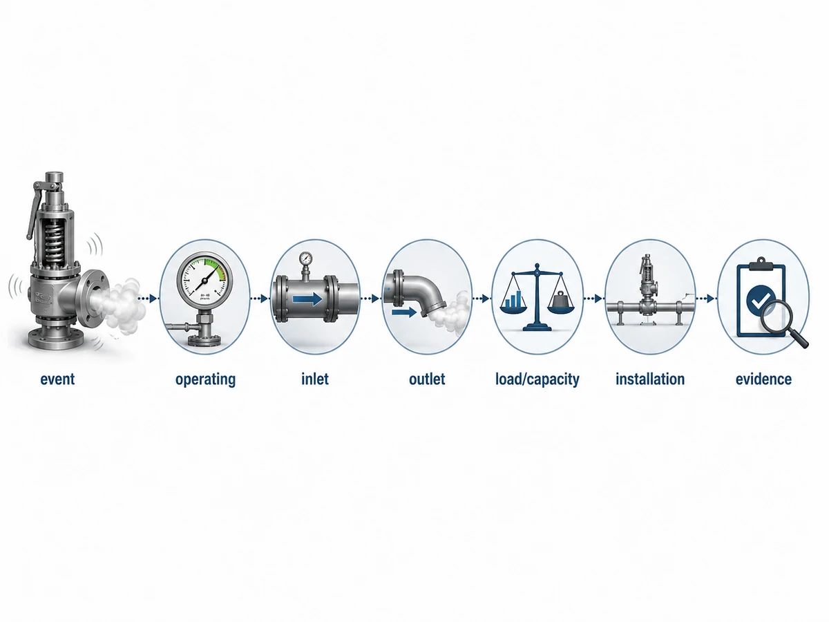
Conceptual diagnosis-first path for investigating spring-loaded safety valve chatter from event evidence to supported conclusion
Conceptual training visual: preserve the event and move from operating evidence to a supported cause before selecting corrective action.

Simplified decision visual; not an automated repair procedure or standards flowchart.

  1. Observed symptom: Describe movement, sound, vibration, leakage and event timing without assigning a cause.
  2. Operating condition: Identify protected equipment, medium/phase, operating pressure and temperature, process state and recent changes.
  3. Inlet arrangement: Review inlet piping, branch configuration, supports and pressure evidence against the applicable project basis.
  4. Outlet and back pressure: Review discharge routing, superimposed and built-up back-pressure information, supports, drains and vents where relevant.
  5. Relieving load and valve capacity: Compare the documented relief scenario and required load with model-level rated capacity data. Connection size alone is not a capacity determination.
  6. Installation and support: Check alignment, mechanical support, thermal movement and any recent modification.
  7. Valve condition: Review identification, configuration, as-found condition, inspection findings, repair history and manufacturer documentation.
  8. Event records: Correlate pressure/time trends, process records and any video, sound or vibration evidence.
  9. Conclusion: State which category is supported, which alternatives remain open, and what qualified engineering review is required before correction.

When the Evidence Is Not Yet Sufficient

A chatter conclusion should remain open when a decision-critical input is missing. Missing evidence is a stop condition for attribution, not permission to assume a cause.

  • No correlated event record: keep the motion classification open until operating and valve records can be compared.
  • Relief scenario not identified: do not infer required relieving demand or normal reseating from sound alone.
  • Valve identity or model capacity not confirmed: do not infer sizing, oversizing or capacity from connection size or appearance.
  • Inlet or outlet configuration undocumented: keep pressure-loss, routing and back-pressure hypotheses conditional.
  • Process change not correlated: do not assign the event to process cycling without time-linked process evidence.
  • Inspection evidence unavailable: do not treat seat or internal damage as proof of the original mechanism.
Decision rule: when one of these gaps remains, document the missing input, preserve the installed evidence and route the case for the applicable engineering or inspection review before selecting corrective action.

When Safety Valve Chatter Requires Immediate Site Review

Severe or repeated chatter can leave the condition of the valve and the installed protection system uncertain. Follow the site’s operating, isolation and emergency procedures and involve the responsible engineer, inspector or authority; a remote symptom description cannot establish that continued operation is safe.

Escalate promptly when

  • disc impacts are severe or repeated;
  • leakage appears after the event;
  • the valve, equipment nozzle or connected piping visibly vibrates;
  • the valve repeatedly operates near normal process pressure;
  • the outlet enters a header with unknown or changing pressure;
  • a new valve, silencer, piping change or process modification preceded the problem.

Do not use a quick field workaround

  • do not tighten or alter the spring as a generic response;
  • do not change set pressure without the approved protection basis;
  • do not block an outlet or bonnet vent;
  • do not add an improvised restriction;
  • do not change discharge piping without engineering review;
  • do not clean or repair away as-found evidence before it is documented.

Three Composite Engineering Scenarios for Training

Composite engineering scenario for training

Scenario A: Restrictive or Problematic Inlet Arrangement

Observed clue: Cycling begins during a relief event after an inlet arrangement changes.

Evidence to preserve/check: Correlate event pressure with the installed inlet path, branch, connection, supports, recent work and available pressure evidence.

Do not assume: An inlet clue proves the valve alone is defective; no dimension or pressure-drop value is assumed.

Engineering direction: Route the supported hypothesis to an inlet-system review.

Composite engineering scenario for training

Scenario B: Capacity and Actual Relieving Demand Mismatch

Observed clue: The valve appears to chatter during a low or changing relief demand.

Evidence to preserve/check: Compare the governing relief scenario and actual process demand with model-level capacity, fluid basis and lift behavior.

Do not assume: Oversizing is a diagnosis; connection size or visual similarity cannot close the review.

Engineering direction: If the evidence supports a mismatch, route it to a sizing and relief-case review.

Composite engineering scenario for training

Scenario C: Discharge and Back-Pressure Interaction

Observed clue: Chatter begins after a discharge route or connected equipment changes.

Evidence to preserve/check: Review outlet configuration, available back-pressure evidence, supports, vents, drains and valve construction.

Do not assume: The presence of back pressure establishes that a bellows or another design will solve the event.

Engineering direction: Route the supported hypothesis to a discharge-system and valve-configuration review.

Match Corrective Action to the Supported Cause

Corrective action follows the supported cause category. It is not a universal response to the sound of chatter.

  • Inlet-side evidence supported: perform an inlet-system engineering review.
  • Load/capacity evidence supported: perform a sizing and relief-case review using manufacturer and project data.
  • Back-pressure evidence supported: perform a discharge-system and valve-configuration review.
  • Installation/support evidence supported: perform an installation review.
  • Process-dynamics evidence supported: perform a process and relief-event review.
  • Valve-condition evidence supported: use the inspection and maintenance route defined by the responsible organization and manufacturer.
Do not change set pressure, spring, valve size, nozzle/orifice, bellows or piping as a generic field workaround. Any modification requires authorized engineering review, applicable project requirements and post-change verification.

Inspection, Test and Document Matrix for a Chatter Investigation

A strong diagnosis connects four evidence domains: the relief scenario, the installed hydraulic system, the selected valve and the valve’s as-found condition. A nameplate, set-pressure certificate or leakage result by itself cannot close the investigation.

Evidence What it can show Why it matters
Nameplate and model documentation Identification, set-pressure basis, connections, spring range and model-level data. Supports replacement and capacity review without assuming that size alone defines performance.
Installation photographs and drawings Inlet/outlet layout, supports, drainage, visible restrictions and recent modifications. Helps screen inlet-loss, discharge/back-pressure and mechanical-load hypotheses.
Pressure/time or process trend Operating pressure, event timing, repeated excursions and reseating behavior. Helps distinguish chatter from process-induced complete cycling.
Relief calculation or datasheet Governing scenario, required relieving load and selected capacity basis. Supports capacity/load comparison and reveals an incomplete protection basis.
Set-pressure/calibration record Opening adjustment and repeatability under the stated test conditions. Shows whether shop behavior differs from field behavior, but does not prove installed stability.
Seat-tightness or leakage record Sealing performance under the stated test conditions. Helps assess post-event seat condition; it is not a sizing or root-cause test.
As-found/as-left and maintenance record Incoming condition, parts changed, contamination, damage, adjustment and final test condition. Preserves cause-versus-consequence evidence and repair traceability.
Discharge-system and header data Outlet resistance, superimposed/built-up back pressure, drainage and simultaneous-event assumptions. Supports the discharge-system branch of the diagnosis.
Management-of-change record Process, capacity, set-pressure, piping, header, silencer, valve-type or material changes. Shows whether the overpressure-protection basis was revalidated after a change.

What to Document Before Repair, Replacement or Engineering Review

Prepare the available evidence package. Required information varies by project, jurisdiction, valve design and relief scenario.

Service and relief basis

  • service medium and phase;
  • operating pressure and temperature;
  • documented set pressure and pressure basis;
  • protected equipment and relief scenario;
  • required relieving capacity where established;
  • applicable project, code and regulatory requirements.

Valve and installed system

  • existing valve designation, nameplate and configuration;
  • inlet piping configuration;
  • outlet/discharge configuration;
  • available back-pressure information;
  • manufacturer documentation;
  • existing datasheet, drawings and photographs.

Event and condition evidence

  • event pressure/time records and process history;
  • inspection findings and repair history;
  • quantity and replacement context where relevant.

This list prepares an engineering review; it is not a universal datasheet or a substitute for a formal relief calculation.

Frequently Asked Questions About Spring-Loaded Safety Valve Chatter

What causes a spring-loaded safety valve to chatter?

Possible categories include inlet-system interaction, load/capacity mismatch, outlet back pressure, blowdown/reseating behavior, installation effects, process dynamics and valve condition. The observed symptom does not prove which category applies. Use the diagnostic sequence and preserve the event evidence.

Is chatter the same as simmer?

No. LESER distinguishes simmer as pre-opening leakage or escape from the seat area, while chatter is repeated unstable cycling with recurring seat contact. The exact terminology depends on the applicable valve documentation and project basis, so confirm it before classifying an event.

Can an oversized safety valve chatter?

A capacity/load mismatch may contribute to instability in some installations, and EPSC lists an oversized relief valve as an influence, but “oversized valve equals chatter” is not a universal rule. Review the actual relief scenario, required demand, model-level capacity, manufacturer guidance and event evidence.

Can inlet pressure loss cause chatter?

Yes, excessive inlet pressure loss can cause chattering according to the LESER installation chapter, which cites API 520 Part II for the inlet-loss discussion. Review the inlet system and event evidence rather than assuming the valve is the only source of the problem.

Can back pressure contribute to chatter?

Yes, but it is a context-dependent discharge-system factor. LESER states that excessive built-up back pressure leads to chattering and that back pressure influences valve function. Review the valve, outlet configuration, operating case and evidence; do not select a design by name alone.

What should be checked before replacing the valve?

Confirm the event, operating condition, inlet and outlet systems, relief case, load/capacity relationship, installation and valve condition. Replacement by appearance, connection size or nameplate similarity alone does not close the diagnosis.

Can a same-size replacement still chatter?

Yes. The same inlet and outlet connection sizes do not guarantee the same effective orifice, spring range, lift characteristic or rated capacity. Compare the old and new model data with the actual relief scenario and event evidence before treating a same-size replacement as equivalent.

Does a passed set-pressure or seat-tightness test prove the installed valve will be stable?

No. Those tests answer different questions under stated test conditions. They do not reproduce the installed inlet pressure loss, outlet back pressure, sustainable process flow, piping loads or process dynamics, so they cannot by themselves prove stable installed relieving behavior.

Technical Review, Standards and Limitations

Technical Review Note

Final case-specific diagnosis depends on actual valve documentation, service conditions, the relief case, manufacturer data, project requirements and inspection evidence. No named technical reviewer or reviewer credential is claimed on this page. Case-specific conclusions require review of the actual installation evidence by the responsible engineering or inspection authority.

This article is engineering guidance for troubleshooting discussion. Final valve selection, adjustment, repair or replacement depends on actual service conditions, the relief scenario, manufacturer data, applicable project specifications and code or regulatory requirements. Local jurisdiction requirements may differ. The article does not reproduce a standard, replace a formal relief calculation, authorize a field modification or establish certification, compatibility or performance for a particular valve.

Standards and Evidence Boundaries

Standards and recommended practices define sizing, installation, product, inspection and repair boundaries; they do not diagnose an individual chatter event without project data. Confirm the edition adopted by the project, jurisdiction and owner-user before applying any requirement.

Official reference Current public status Use boundary in this article
API 520 Part I API identifies the 10th Edition as published. Sizing and selection framework; compare required and documented valve capacity on the correct fluid and pressure basis.
API 520 Part II API identifies the 7th Edition as published and notes an engineering-analysis route for installation review. Inlet/outlet installation context. Do not copy a single pressure-loss percentage into every project without the full conditions and adopted edition.
API 527 API’s current digital catalog lists Edition 5. Seat tightness under stated test conditions; not a sizing, capacity or chatter root-cause test.
ASME BPVC Section XIII ASME lists the 2025 edition. Overpressure-protection rules and applicable design/testing/marking/capacity/installation requirements; do not infer product certification without model records.
ISO 4126-1:2013 + Amendment 1:2016 ISO states the 2013 edition was reviewed and confirmed in 2025 and remains current. Product requirements for safety valves where adopted; ISO explicitly identifies Part 1 as a product standard, not an application standard.
NBIC 2025, Part 4 The National Board lists the 2025 edition, including Part 4 for pressure relief devices. Inspection/repair context where applicable. Repair authorization does not replace relief sizing or installed-system review.

Technical References

Public terminology on this page is paraphrased from the cited sources. Applicable valve documentation, project requirements and governing documents control the installed case.

Prepare a Technical Review Package for a Chattering Safety Valve

Provide the available service and relief-case data, operating conditions, documented set pressure, valve nameplate and configuration, inlet/outlet arrangement, back-pressure information, event records, inspection findings, manufacturer documents and applicable project requirements. The responsible engineer, owner-user, inspector or authority determines which inputs are required for the specific case.

咨询工程师