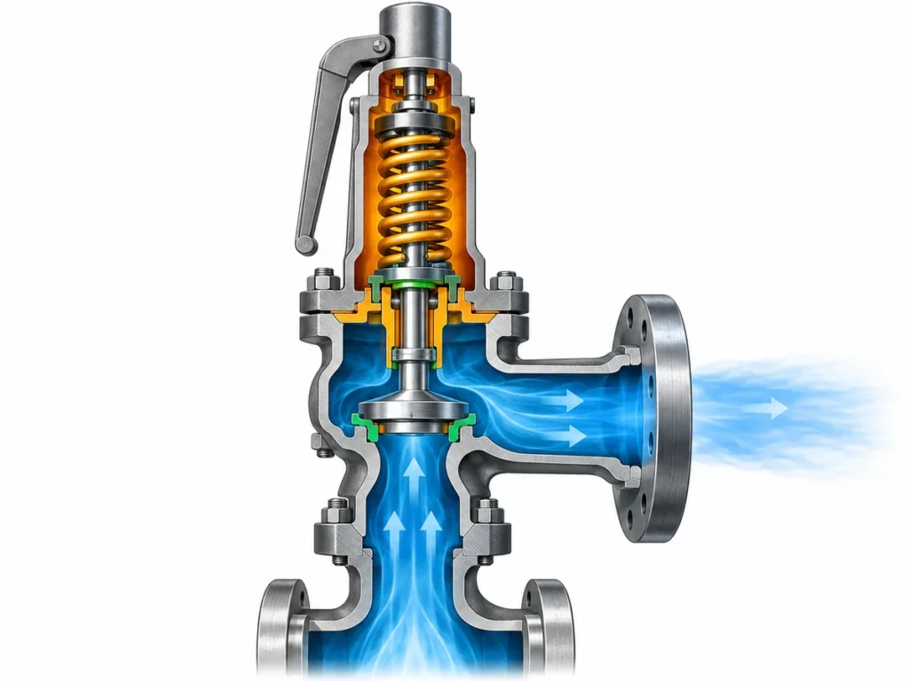
Entenda como viscosidade, resfriamento, projeto jaquetado, capacidade, contrapressão e instalação afetam a seleção de válvulas de segurança para betume, asfalto e óleo pesado.

Válvulas de segurança para sistemas de betume, asfalto e óleo pesado não devem ser selecionadas começando pela pergunta “Preciso de uma válvula jaquetada?”. A primeira tarefa é definir o cenário de alívio real, a condição do fluido nas condições de alívio e se o caminho completo desde o equipamento protegido até a válvula pode permanecer capaz de aliviar. A construção jaquetada pode ser uma medida importante de gerenciamento térmico, mas não substitui o dimensionamento, a verificação de capacidade, a análise de contrapressão, a seleção de materiais ou engenharia de instalação.
Essa distinção é importante porque betume, asfalto e óleos pesados são serviços fortemente sensíveis à temperatura. À medida que a temperatura cai, a viscosidade pode aumentar acentuadamente, e alguns produtos podem endurecer, depositar ou se tornar difíceis de mover. O comportamento exato depende do grau, da composição e do histórico de operação; não existe uma única viscosidade ou “temperatura de solidificação” que possa representar com segurança todos os serviços de asfalto ou óleo pesado.
A questão de engenharia, portanto, é mais ampla do que o tipo de válvula. É se o sistema de alívio de pressão selecionado pode permanecer aberto, com capacidade de fluxo e corretamente dimensionado sob as condições reais de operação, espera e alívio.
Válvulas de segurança para betume: comece pela condição do fluido
“Betume”, “asfalto” e “óleo pesado” são rótulos úteis de serviço, mas não definem um dever de válvula de alívio.
Duas correntes de óleo pesado podem se comportar de maneira muito diferente na mesma temperatura nominal. Da mesma forma, um grau de asfalto pode ainda fluir facilmente a uma temperatura na qual outro se torna muito mais resistente ao movimento. Alguns óleos pesados também podem apresentar comportamento não newtoniano, de modo que uma única suposição genérica de viscosidade pode não descrever com precisão a condição de alívio.
Para a seleção de alívio de pressão, as perguntas úteis são mais específicas:
- Qual produto, grau ou composição exato está sendo manuseado?
- Espera-se que o fluido de alívio seja líquido, vapor, mistura gás-líquido ou outra condição de fase?
- Quais são as temperaturas normais de operação e de alívio?
- Que temperaturas podem ocorrer durante a partida, parada ou standby prolongado?
- Há informações disponíveis sobre viscosidade versus temperatura para o fluido de processo real?
- Há evidências de endurecimento, formação de parafina, deposição, coqueificação, cristalização ou outros mecanismos de restrição neste serviço?
As respostas afetam mais do que a escolha entre uma válvula padrão e uma válvula jaquetada. Elas podem alterar a base de dimensionamento, a probabilidade de restrição na entrada ou no caminho de fluxo da válvula, a análise de material e sede, e a quantidade de gerenciamento térmico que o sistema instalado pode necessitar.
É também aqui que a terminologia importa. Buscas por “válvula de alívio para asfalto” frequentemente retornam dispositivos internos de bypass ou alívio de bomba. Esses dispositivos podem proteger uma bomba contra pressão diferencial excessiva, mas não são automaticamente equivalentes a uma válvula de segurança ou válvula de alívio de pressão que protege um vaso, tubulação ou outro sistema de pressão. A função de proteção deve ser identificada antes que a válvula possa ser selecionada.
Siga o caminho completo de alívio para resfriamento, restrição e risco de deposição
Uma válvula de alívio de pressão só protege o equipamento se a pressão do sistema protegido puder alcançar a válvula e a vazão de alívio requerida puder passar pelo dispositivo e pelo caminho de descarga.
Isso torna o caminho completo de alívio importante em serviços sensíveis à temperatura.
Uma análise útil normalmente começa no bocal ou ramal do equipamento e segue o caminho através de:
- a conexão do equipamento protegido;
- a tubulação de entrada e quaisquer restrições;
- a entrada da válvula e o passageiro interno de fluxo;
- a saída da válvula; e
- o arranjo de descarga a jusante, onde o meio de processo pode entrar ou influenciá-lo.
O objetivo não é presumir que todas as partes do sistema devam ter traçagem de vapor ou jaqueta. É identificar onde resfriamento, material estagnado, depósitos ou restrições geométricas podem se tornar relevantes para a instalação específica.
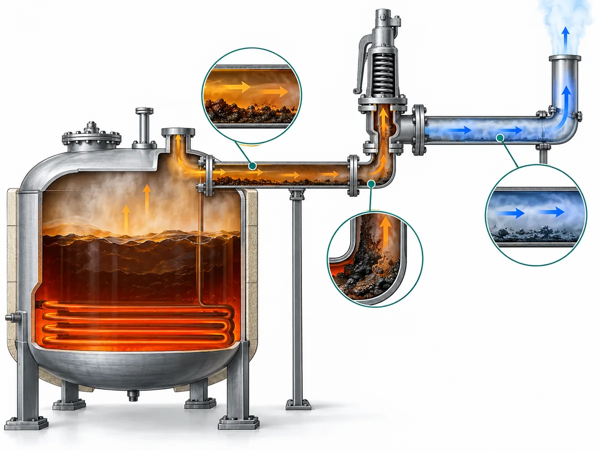
Considere um vaso representativo de asfalto aquecido com uma válvula de segurança conectada por um ramal de processo curto. Durante a operação normal, o conteúdo do vaso pode ser mantido a uma temperatura que mantém o material facilmente fluido. Isso não significa automaticamente que o ramal e a válvula permaneçam na mesma condição durante um longo período de parada. Se uma seção não aquecida esfriar substancialmente, o material ali presente pode se tornar muito mais viscoso ou formar depósitos.
A consequência de engenharia não é simplesmente “adicionar traçagem térmica”. A sequência correta é determinar se a condição é crível, onde ela pode ocorrer e se poderia restringir a comunicação de pressão ou o fluxo de alívio. Só então o projeto pode decidir se isolamento, traçagem, jaqueta na válvula, um arranjo diferente, procedimentos operacionais ou outra medida é apropriado.
A mesma disciplina se aplica a jusante. Alguns serviços podem exigir uma revisão de resfriamento, drenagem ou acúmulo no sistema de descarga, mas isso não sustenta uma regra universal de que toda saída de válvula de segurança de óleo pesado deva ser aquecida. O destino real da descarga, a geometria da tubulação, a contrapressão e a exposição ao fluido de processo determinam o que precisa ser verificado.
Decida quando a construção jaquetada pertence à solução — e o que ela não pode resolver
A válvula de segurança jaquetada oferece uma forma de transferir calor para uma região definida do corpo da válvula ou da estrutura associada. Para meios viscosos, pegajosos, cristalizantes ou propensos à solidificação, isso pode ajudar a manter uma condição de fluido mais favorável na porção do caminho de alívio coberta pela jaqueta.
Essa é uma função de engenharia legítima, mas seu limite deve ser claro.
A jacket normally heats the region designed into the valve. It does not automatically maintain the temperature of the vessel nozzle, upstream branch, inlet piping or discharge piping. If those areas are also vulnerable to cooling or deposits, their thermal condition has to be reviewed separately.
The most useful selection question is therefore not:
Is this a heavy-oil service?
E sim:
Which parts of the relief path are at risk of losing the fluid condition required for reliable pressure communication and flow, and what thermal-management measures are justified at those locations?
A jacketed valve becomes a stronger candidate when the evidence shows that maintaining temperature around the valve flow path is important. The exact jacket arrangement, however, is product-specific. Jacket coverage, utility connections, allowable utility conditions and the type of heating medium cannot be inferred from the word “jacketed” alone.
Heating media can also differ between designs and projects. Steam may be used in some systems, while other applications may use a different approved heating medium. The allowable pressure and temperature of the jacket circuit must come from the exact manufacturer data and project design basis.
There is another practical distinction: heating and flushing are different functions. Some jacketed-valve designs may incorporate auxiliary connections intended for specific maintenance or flushing arrangements, but their presence and purpose must be confirmed from the exact drawing. They should not be assumed for every jacketed valve.
ZOBAI’s product catalog includes a ZBNJ jacketed safety-valve family, including cataloged configurations with a jacketed body and auxiliary connections. That confirms the existence of the product family, not the suitability of a particular ZBNJ model for every bitumen, asphalt or heavy-oil duty. Exact pressure and temperature limits, jacket conditions, materials, connections, capacity basis and certification must be confirmed against the selected model and current documentation.
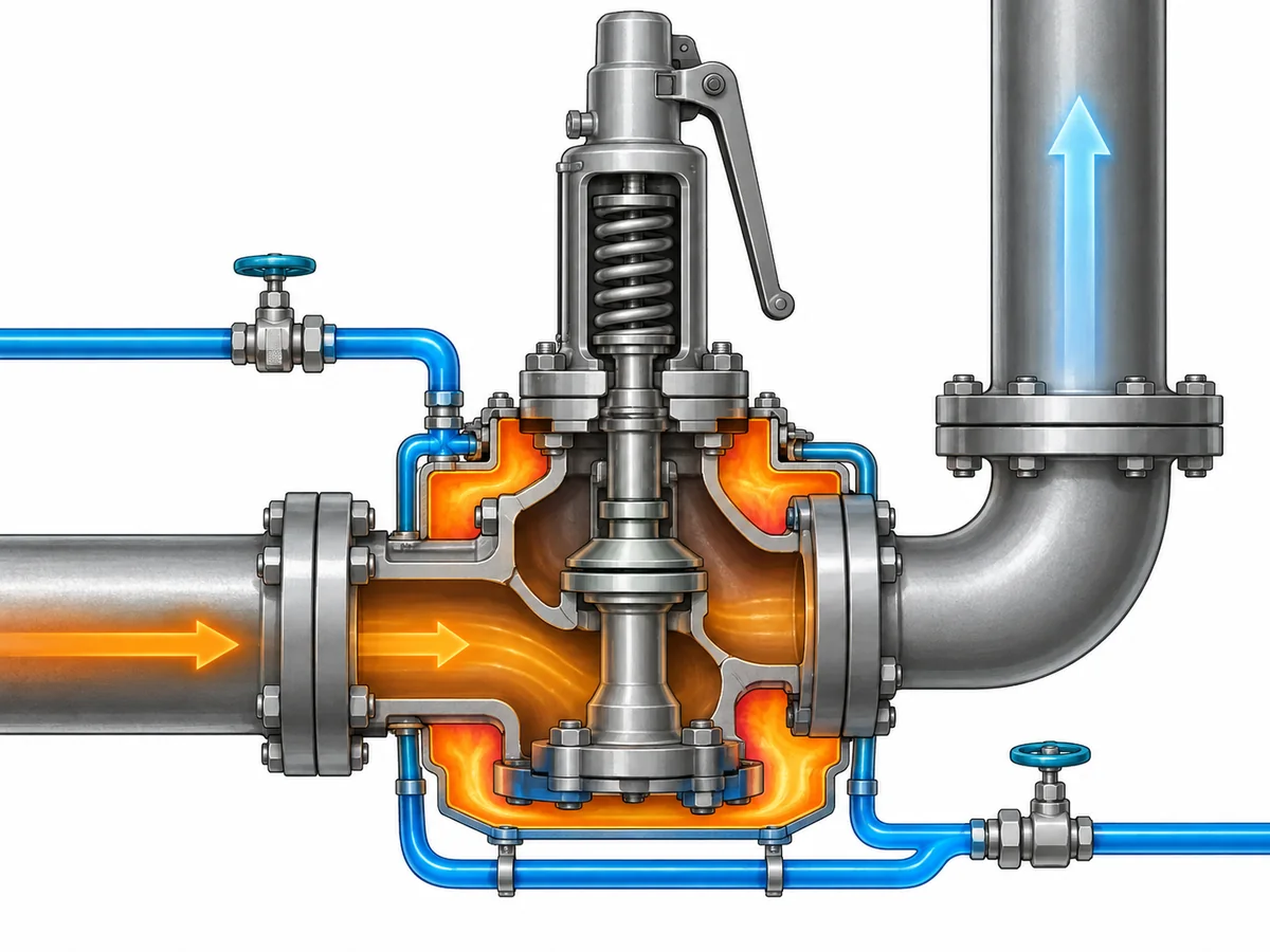
The key boundary is simple: a jacket can address a defined thermal problem; it does not by itself prove that the pressure-relief system is adequately sized or correctly installed.
Keep thermal management separate from sizing, capacity and back pressure
Thermal management answers one question: can the process medium remain in a condition that allows the intended relief path to function?
Pressure-relief sizing answers another: can the selected valve pass the required relieving load under the specified relieving conditions?
Those questions interact, but they are not interchangeable.
For viscous liquid service, actual fluid viscosity can affect the sizing calculation. Recognized pressure-relief sizing methods account for viscosity where applicable rather than treating every liquid as an inviscid fluid. The exact correction method, coefficients and acceptance basis must follow the governing standard, the fluid data and the selected manufacturer’s documented performance basis.
That leads to several distinctions that should remain separate throughout the specification:
| Questão de engenharia | O que deve ser estabelecido | What does não prove it |
|---|---|---|
| Required relief duty | Governing overpressure scenario and required relieving rate | Valve connection size |
| Área de descarga necessária | Applicable sizing method using actual relieving conditions | A jacketed body |
| Capacidade da válvula | Documented or certified capacity for the exact selected valve and applicable basis | Similar appearance or nominal size |
| Thermal suitability | Fluid behavior and temperature condition through the relevant relief path | Capacity calculation alone |
| Back-pressure suitability | Outlet system and valve configuration under actual back pressure | The word “jacketed” |
| Inlet suitability | Pressure communication, geometry and inlet-loss condition | Matching inlet flange size |
Required relieving capacity is therefore not the same thing as the selected orifice, and neither is automatically the same as the certified or documented capacity of a particular valve. The calculation establishes what the system requires. Product data establish what the exact selected valve can deliver under its applicable performance basis.
The pressure definitions also need to remain distinct. Operating pressure, design pressure or MAWP, set pressure, allowed overpressure or accumulation, and relieving pressure serve different purposes in the relief design. Changing the thermal arrangement does not remove the need to establish those values correctly.
Inlet pressure loss is another independent check. A pressure-relief valve depends on pressure being transmitted from the protected equipment to its inlet without an unacceptable loss that changes its behavior. In a high-viscosity service, both the fluid properties and the inlet arrangement can matter. A heated valve body cannot compensate for a fundamentally unsuitable inlet path.
The outlet side requires the same discipline. Built-up and superimposed contrapressão can influence valve behavior and capacity depending on the configuration. A jacketed conventional valve, balanced bellows valve or pilot-operated valve should not be selected simply by assuming that one configuration “solves” back pressure.
Safety and code boundary: This article explains application and specification logic; it does not replace the governing relief calculation, the applicable code or standard, manufacturer capacity data, or project acceptance. API 520 e API 521 can be relevant engineering references where they apply, but the governing edition, jurisdiction and project requirements must be confirmed for the actual installation.
Screen materials, trim, seats and maintenance against the real service
Once the thermal and capacity questions are separated, material and maintenance decisions become easier to frame correctly.
A body material alone does not establish service suitability. Bitumen, asphalt and heavy-oil applications may expose different components to different combinations of process medium, contaminants, temperature and heating utility. Depending on the valve design, the review may include:
- body and nozzle materials;
- disc and guide materials;
- spindle and spring environment;
- bellows material where a bellows design is used;
- seat and seal construction;
- gasket materials;
- jacket materials and utility compatibility; and
- any auxiliary flushing or drain connection materials.
The correct combination depends on the actual medium and temperature. A generic statement such as “stainless steel is suitable for heavy oil” is too broad because it says nothing about the composition, contaminants, temperature, mechanical requirements or project specification.
Maintenance history can also be valuable evidence. If an existing installation repeatedly shows hardened material, deposits or restricted passages in a particular location, that observation can help identify where the thermal or mechanical design needs further review. It should not be treated as proof that every similar service will fail in the same way.
The same applies to seat leakage or sticking. Deposits may be one plausible contributor in dirty or viscous service, but leakage, simmer, unstable operation or failure to reseat can have other causes. Troubleshooting should distinguish symptoms from causes rather than assuming that the process medium explains every problem.
For a new project, the specification should therefore focus on the conditions that change the decision rather than on a generic material list. For an existing installation, inspection findings, maintenance records and the actual pattern of deposits can provide additional evidence for that review.
Specify the system, not just the valve
A useful RFQ for bitumen, asphalt or heavy-oil service should describe the relief duty and thermal environment, not simply request a “jacketed asphalt safety valve.”
Before configuration and product selection are finalized, the engineering team should normally provide the information that materially affects the decision.
Protection and process basis
- Protected equipment or system.
- Governing relief scenario.
- Process medium, grade and composition where relevant.
- Expected phase at relieving conditions.
- Normal operating pressure.
- Design pressure or MAWP.
- Required set pressure.
- Required relieving rate and the calculation basis.
- Relieving pressure and temperature.
Fluid and thermal data
- Viscosity or other relevant rheological data at the temperatures that matter to the project.
- Known hardening, wax, deposit, crystallization or solidification behavior where applicable.
- Normal process temperature.
- Startup, shutdown and standby temperatures if they materially change fluid condition.
- Existing insulation, heat tracing or jacket arrangement.
- Heating-medium type and available utility conditions where a jacket is being considered.
Dados de instalação
- Equipment nozzle and inlet arrangement.
- Inlet and outlet connection requirements.
- Inlet pressure-loss information where available.
- Superimposed and expected built-up back pressure.
- Discharge destination and piping arrangement.
- Drainage or accumulation concerns where relevant.
- Any known location where material has previously cooled or deposited.
Valve and material requirements
- Required valve configuration if already specified by the project.
- Body, trim, bellows, seat, seal and gasket requirements where applicable.
- Existing valve datasheet, nameplate or drawing for replacement work.
- Required inspection, testing and documentation.
- Governing code, standard and project specification.
Not every project needs every field at the same level of detail. The point is to identify the inputs that can change the calculation, configuration or acceptance decision before a model is quoted or ordered.
A supplier can then review the service in a logical sequence: confirm the protection basis, evaluate the fluid and thermal conditions, determine the required relieving capacity, assess configuration and back pressure, confirm materials and installation requirements, and finally verify the exact valve against manufacturer data.
That process is much safer than selecting by medium name or connection size alone.
Engineering review next step: Send the protected equipment, governing relief scenario, medium and phase, operating and relieving temperatures, pressure basis, required relieving capacity, viscosity or relevant fluid-property data, back pressure, inlet/outlet arrangement, thermal-management conditions and applicable project requirements for model-level review. Final valve suitability, jacket conditions and documented capacity should be confirmed against the selected product and governing project basis.
Need a model-level review? Submit the actual relief duty, fluid properties, pressure basis, temperature conditions and piping information before final valve selection.