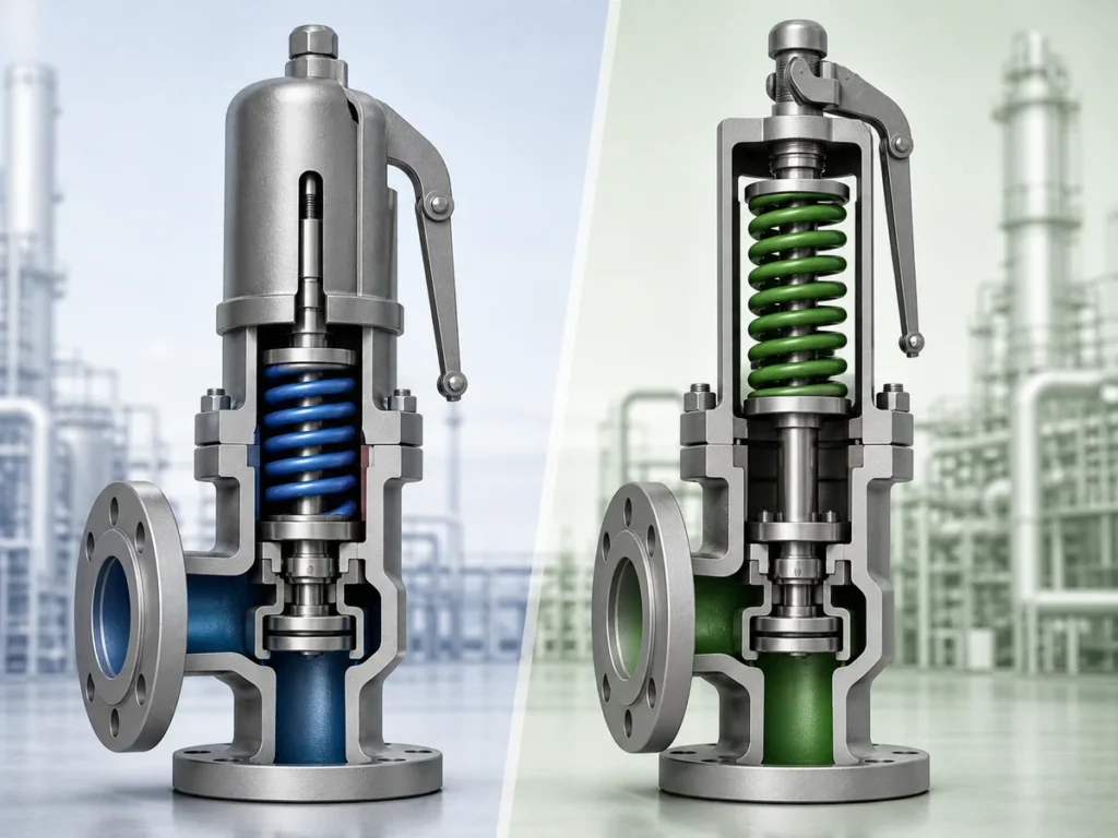
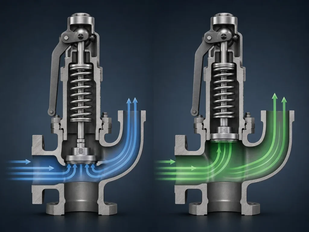
A trapped-liquid LPG relief review starts with the piping boundary, not with a valve model. First determine whether liquid can be isolated, identify the exact section enclosed by that isolation, establish a credible condition that can warm the trapped liquid, and define where relief flow is intended to go. Device suitability and the installed relief …

Uma revisão de alívio para LPG com líquido retido começa pelo limite da tubulação, não pelo modelo da válvula. Primeiro, determine se o líquido pode ser isolado, identifique a seção exata delimitada por esse isolamento, estabeleça uma condição plausível que possa aquecer o líquido retido e defina para onde o fluxo de alívio deve ser direcionado. A adequação do dispositivo e o caminho de alívio instalado só podem ser avaliados com base nesse escopo do sistema.
Neste contexto, alívio térmico descreve a função de proteção associada ao aquecimento de um volume de líquido retido. Válvula de alívio hidrostático is also established terminology in LP-Gas regulatory and standards contexts. Neither term should be reduced to a generic LPG safety-valve label: the actual liquid-service duty still has to be confirmed.
The scope here is blocked-in liquid LPG piping. Storage-vessel relief, vessel fire scenarios, vacuum protection and general pressure-relief sizing use different protected boundaries or design bases and remain separate engineering subjects.
How Does a Liquid LPG Line Become Blocked In?
Limites de Isolamento Que Podem Criar uma Seção de Líquido Retido
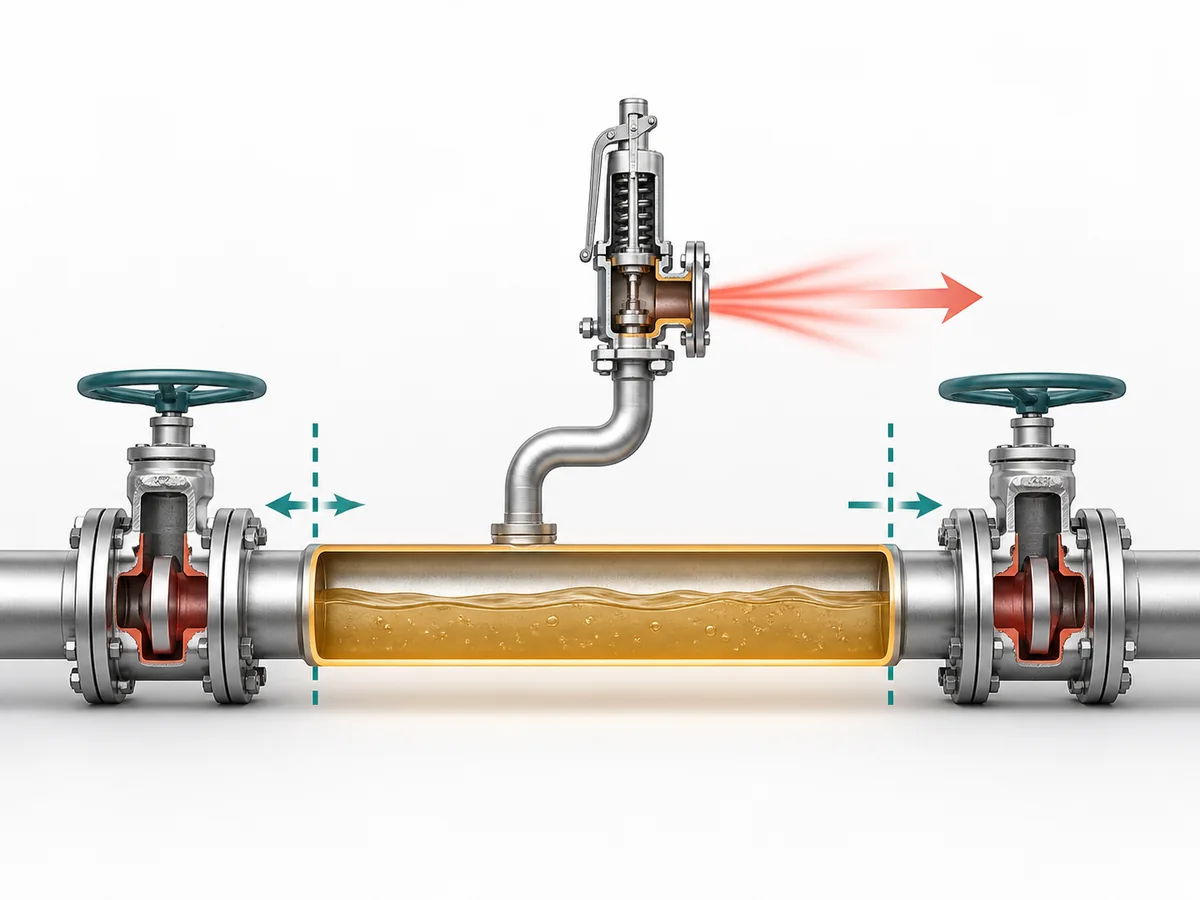
Uma seção retida candidata existe quando uma parte da tubulação cheia de líquido pode ser fechada por limites de isolamento efetivos. Fechar válvulas ou outros pontos de isolamento efetivos em ambos os lados pode remover o caminho normal para o líquido se mover para o sistema circundante.
UK Health and Safety Executive (HSE) process-pipework guidance explicitly recognizes liquid being trapped between closed isolation boundaries. U.S. Occupational Safety and Health Administration (OSHA) LPG requirements separately address liquid LPG trapped between shutoff boundaries within their applicable scope. The practical task is therefore to locate the actual enclosed liquid section rather than treat the complete LPG installation as one protected volume.
A presença de dois pontos de isolamento aparentes não é, por si só, a conclusão. A engenharia ainda precisa estabelecer que a seção contém líquido no estado relevante e que esses limites podem realmente isolá-la.
Estados de Válvula em Operação Normal Versus Manutenção
A configuração de fluxo normal pode não revelar todas as condições de bloqueio. Partida, parada, manutenção ou outro estado operacional legítimo pode alterar quais limites estão abertos e quais seções ficam isoladas.
Revise o estado da válvula juntamente com a condição do líquido. Uma pergunta mais útil do que “Esta válvula está normalmente aberta?” é:
Um estado operacional ou de manutenção relevante pode deixar líquido confinado dentro desta seção?
Isso evita que a revisão de alívio seja baseada apenas na imagem de fluxo normal, ignorando um estado de isolamento diferente que altera o limite protegido.
Defina a Seção Retida Antes de Discutir o Dispositivo de Alívio
Desenhe o limite protegido antes de avaliar o dispositivo de alívio. O limite deve identificar a seção cheia de líquido, os pontos de isolamento efetivos e a conexão através da qual o caminho de alívio pretendido permaneceria disponível.
- Confirme a seção que pode reter líquido.
- Confirme os pontos de isolamento que podem fechá-la.
- Confirme o estado operacional ou de manutenção em que esse fechamento ocorre.
- Confirme se a conexão de alívio pretendida permanece conectada a essa seção no mesmo estado.
Uma declaração geral de que o sistema LPG mais amplo já contém equipamentos de alívio de pressão não responde a essas perguntas para um segmento bloqueado separado.
Por que o aquecimento de um segmento de líquido LPG preso pode criar uma preocupação de sobrepressão?
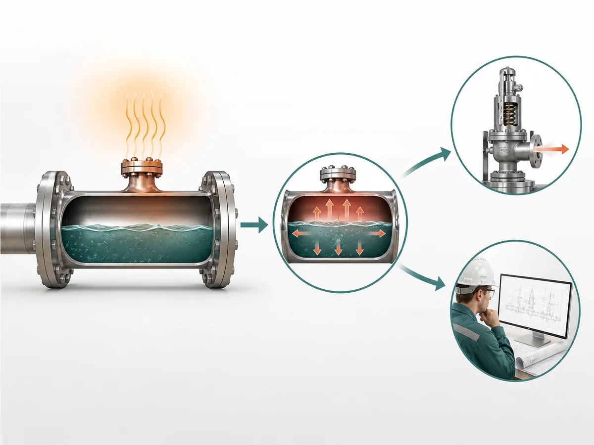
O mecanismo de expansão térmica
Quando a seção permanece hidraulicamente conectada ao processo ao redor, o líquido pode se mover conforme as condições do sistema mudam. Uma vez que o líquido é confinado entre limites efetivos, essa liberdade é restrita.
A orientação de tubulação de processo da HSE identifica a mudança de temperatura e a expansão térmica de líquido preso como uma preocupação potencial de perda de contenção. O Conselho Regulador de Petróleo e Gás Natural da Índia (PNGRB) também aborda a proteção contra expansão térmica para LPG líquido preso dentro de seu escopo regulatório.
A decisão de engenharia imediata não é, portanto, um cálculo de capacidade. É se a combinação de confinamento de líquido e uma condição de aquecimento plausível cria um dever de alívio térmico ou hidrostático que requer engenharia adicional.
Por que esse dever é diferente do alívio de incêndio em vasos
O sistema protegido define o problema. Para uma linha bloqueada, o ponto de partida é um segmento de tubulação de líquido confinado e uma condição de aquecimento que afeta esse segmento. Um cenário de emergência ou incêndio em vaso de armazenamento começa com um sistema protegido diferente e uma base de alívio diferente.
O fato de que ambos os problemas podem envolver equipamentos de alívio de pressão não torna um substituto para o outro. Um sistema de alívio de vaso não deve ser assumido para proteger uma linha de líquido que pode ser isolada fora do limite efetivo de alívio do vaso.
O que significa “aquecimento crível” nesta fase
Uma condição de aquecimento crível é uma condição real do projeto capaz de aumentar a temperatura do líquido enquanto a seção identificada permanece isolada. Ela deve vir da base de instalação e operação, e não de um exemplo genérico de alívio térmico.
HSE guidance identifies external heat, temperature gradients and temperature cycling as conditions that may deserve review where they apply. OSHA also recognizes abnormal external heat exposure in defined LPG installation contexts. These sources support the need to examine real warming mechanisms; they do not establish one universal list for every LPG line.
A sequência útil é, portanto: primeiro estabelecer que o segmento pode ser isolado e, em seguida, identificar a condição que pode aquecê-lo enquanto isolado. Se a base de aquecimento for desconhecida, mantenha-a como uma entrada de projeto não resolvida, em vez de substituí-la silenciosamente por um cenário assumido.
Como você define o segmento protegido e a condição de aquecimento plausível?
Estabelecer os limites físicos do segmento protegido
Comece pela linha ou seção do equipamento que contém líquido e trace em ambas as direções até que os limites efetivos de isolamento sejam compreendidos. Em seguida, localize a conexão de alívio pretendida em relação a esses limites.
A revisão de limites deve responder:
- Qual seção física pode reter líquido?
- Quais pontos de isolamento podem envolver essa seção?
- Sob qual estado relevante da válvula ocorre o enclausuramento?
- A conexão de alívio pretendida permanece no lado protegido desses limites?
Um P&ID é um ponto de partida, não um substituto para a filosofia de operação e manutenção. Quando o estado do desenho e a prática real de isolamento ainda não estão conciliados, o limite protegido permanece não resolvido.
Verifique quais estados da válvula podem realmente isolá-la
Revise os estados que podem alterar o limite deste segmento, em vez de expandir a tarefa para um inventário de válvulas de toda a instalação. Uma linha pode permanecer conectada durante a operação normal, mas ficar enclausurada durante a manutenção. Por outro lado, os pontos de isolamento mostrados em um desenho não comprovam que o líquido esteja retido em todos os estados.
Ask whether this actual valve state can confine liquid between effective boundaries while the section is exposed to the warming condition under review.
A “yes” identifies a scenario requiring thermal-relief review. An unknown valve state, liquid condition or boundary remains an information gap. It should not be converted into either a positive or negative selection conclusion.
Identify the Warming Condition Engineering Must Evaluate
Pair the protected boundary with the project condition that can warm the liquid while that same boundary exists. This avoids evaluating a warming condition that occurs only when the line is open, or an isolation state that is never exposed to the proposed warming mechanism.
The decision basis can be expressed qualitatively as:
protected segment + relevant isolation state + credible warming condition.
This is a boundary-definition framework, not a sizing formula. Detailed relief calculations belong after the scenario and its project inputs have been established.
How Should the Thermal-Relief Discharge Path Be Defined?
Identify the Intended Discharge Destination
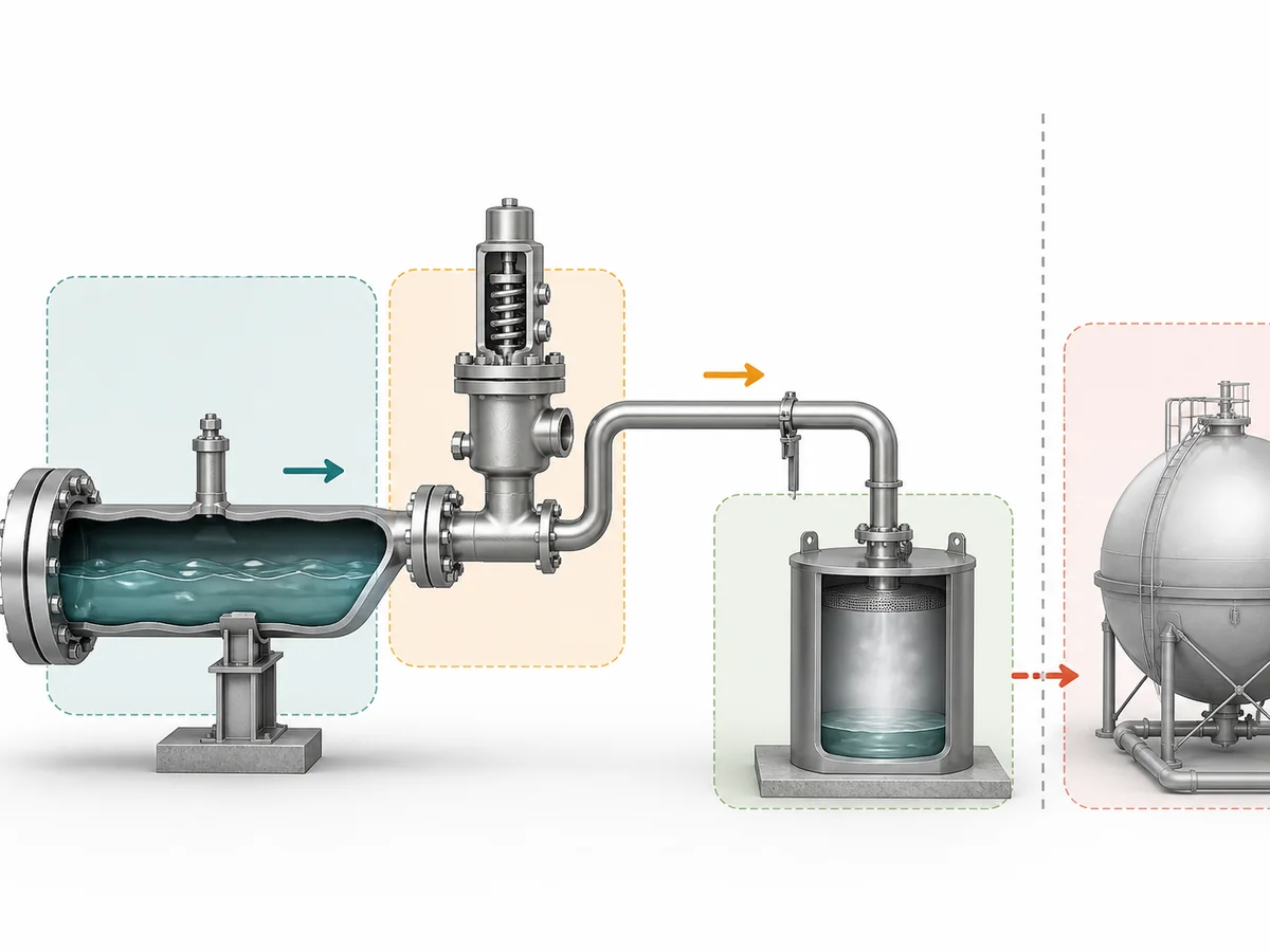
A relief device is not fully defined by its connection to the trapped segment. The engineering basis also needs to state where relieved LPG is intended to go.
OSHA’s LPG requirements provide a scope-specific example in which hydrostatic relief from specified liquid piping is directed to a safe atmosphere. That requirement should not be generalized beyond its applicable jurisdiction and system scope. Where another pressure-containing or product-retaining system is proposed as the receiving destination, the connected-system conditions must be carried into the appropriate engineering review rather than treated as automatically acceptable.
The practical conclusion is that the project must establish the intended destination under its applicable requirements and receiving-system conditions before treating the relief path as resolved.
The relief path remains unresolved until the receiving destination and its applicable project boundary are known.
Identify Downstream Pressure or Back-Pressure Conditions
When the outlet enters another pressure-containing or product-retaining system, that receiving system can impose conditions at the relief-device outlet. Those conditions are therefore part of the engineering input to later device and installation review.
The project package should identify the receiving system and the relevant downstream pressure condition rather than describing the outlet only as “closed” or “connected.” Detailed acceptability of the connected network remains a separate downstream-system analysis.
American Petroleum Institute (API) pressure-relief installation guidance treats installed relief arrangements as an engineering-analysis subject. This page therefore does not establish an allowable back pressure, size a return path, or design a disposal, recovery or shared relief network; those decisions remain with the appropriate downstream engineering owner.
Route Closed-System Questions to the Appropriate Downstream Analysis
A product-retaining or other closed receiving system should not be interpreted as acceptable merely because a physical connection is available. The relevant question for this article is whether the destination and downstream condition are sufficiently defined for the next engineering decision.
- If the destination is not established, retain it as an RFQ or project-data gap.
- If the outlet connects to another pressure-containing system, identify the downstream condition for the responsible system analysis.
- If acceptability depends on connected-network hydraulics, route that question to the downstream relief-system owner instead of solving it inside this page.
Phase change remains conditional. If project-specific fluid and downstream conditions make a phase transition material to the relief analysis, it should be addressed in the separate sizing or downstream-system review. It is not treated here as a universal selection gate for every trapped-liquid LPG line.
How Do You Verify Liquid-Service Suitability and Keep the Relief Path Available?
Confirm That the Proposed Device Is Intended for the Required Liquid-Service Duty
Broad LPG service wording is not enough to establish suitability for a blocked-in liquid thermal or hydrostatic relief duty.
UL Standards & Engagement recognizes hydrostatic relief valves as an LP-Gas relief-device category, while PNGRB separately addresses suitable thermal pressure relief where liquid can be trapped. The procurement implication is limited but important: suitability for this duty should be supported directly rather than inferred from a generic LPG valve-family description.
Device review therefore starts with the system basis already defined in the earlier sections: the protected segment, liquid condition, warming scenario, intended discharge destination and relevant downstream condition. Product-specific suitability can then be confirmed against that basis by the responsible supplier or engineering reviewer.
Check Whether Isolation Can Disable the Relief Path
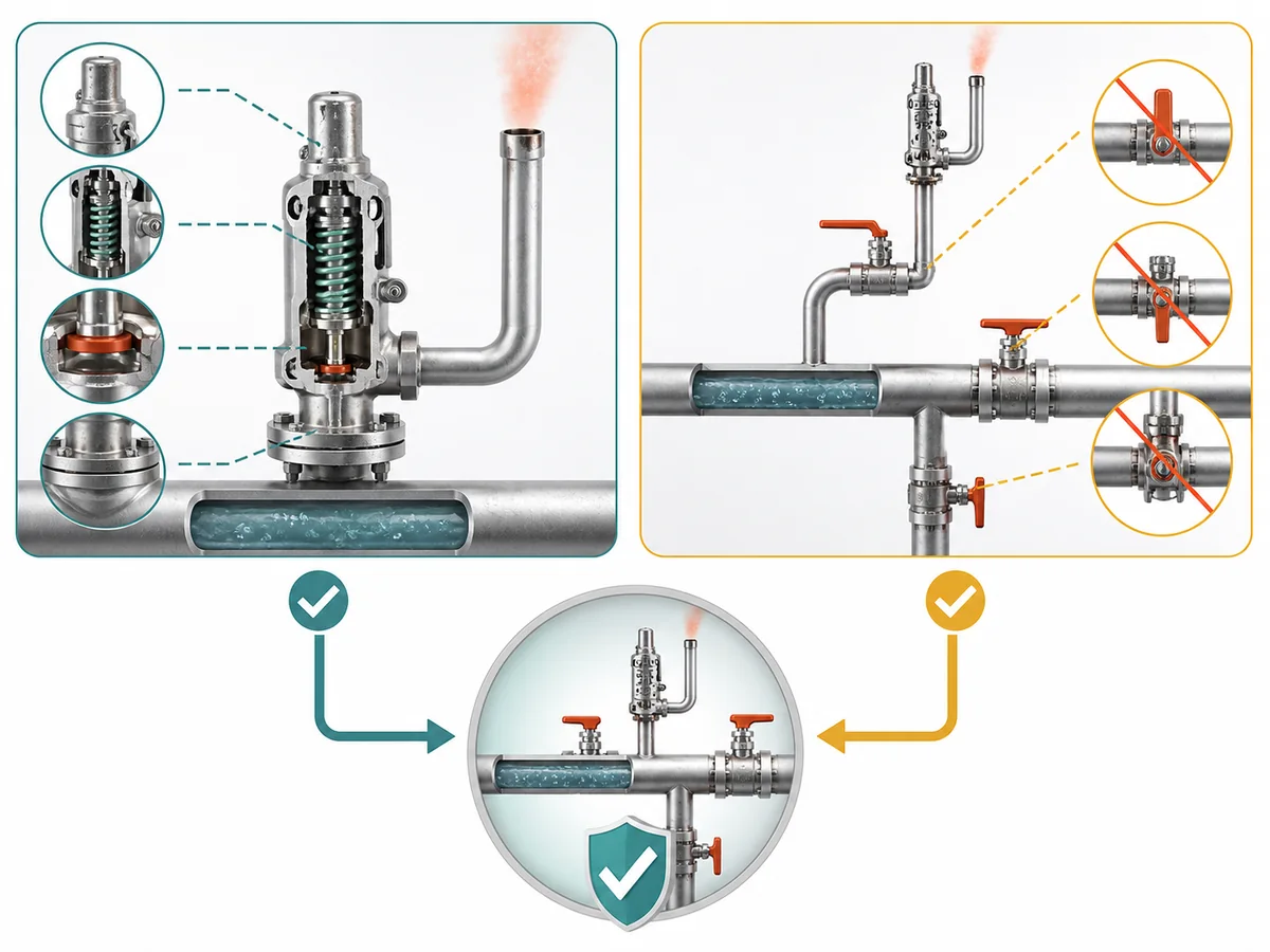
Device suitability does not protect the trapped segment if the installed arrangement can disconnect that device from the segment in the state when relief is needed.
Within the directly frozen U.S. OSHA LP-Gas scope, arrangements that can isolate a relief device from protected equipment or piping are restricted unless the required relief path is preserved. HSE process-pipework guidance separately identifies isolation-valve location as an important consideration where trapped-liquid thermal expansion is possible.
For each relevant operating or maintenance state, check whether an effective isolation boundary can separate the intended relief connection from the trapped liquid segment.
If it can, the arrangement is not resolved by this article. Its acceptability has to be established under the applicable project and jurisdictional requirements. The exact acceptable isolation arrangement is deliberately not generalized here.
Keep Installation Review Separate From Generic Valve Selection
Two confirmations are required, and one cannot substitute for the other:
- Duty suitability: evidence for the proposed device supports the intended trapped-liquid LPG thermal or hydrostatic service.
- Path availability: the installed isolation arrangement keeps the intended relief path connected to the protected segment in the relevant state, subject to applicable project requirements.
Keeping these questions separate prevents a common reasoning error: choosing a nominally relevant device and then treating installation availability as automatically proven.
What Information Should Go Into an LPG Thermal-Relief RFQ?
The RFQ should allow each responsible party to see what is already established, what still needs confirmation and who owns the unresolved decision. It should not force the supplier to reconstruct the protected boundary from a generic valve description.
| Input group | Informações do projeto | Primary confirmation responsibility | Decision supported |
|---|---|---|---|
| Protected segment | P&ID or line identification, liquid-containing section and effective isolation boundaries. | Project or piping engineering establishes the system boundary. | Defines exactly what section requires review. |
| Isolation states | Relevant normal, operating and maintenance valve states. | Project or operating basis establishes when the section can become enclosed; installation review checks relief-path availability. | Connects the protected boundary to the state in which relief may be required. |
| Fluid and operating basis | Available LPG fluid definition, confirmation of liquid service, and the project’s pressure and temperature basis. | The project supplies the service basis; the device reviewer evaluates suitability against it. | Prevents device suitability from being inferred from a generic LPG label. |
| Credible warming | The actual project condition capable of warming the liquid while the segment is isolated. | The project establishes the credible scenario. | Defines the thermal-expansion duty that later engineering must evaluate. |
| Relief destination and downstream condition | Proposed relief location, intended receiving destination and relevant downstream pressure condition. | The project identifies the destination; the responsible downstream-system owner resolves connected-system effects where required. | Separates valve-duty definition from closed-system or downstream-network analysis. |
| Compatibility and project requirements | Applicable fluid-compatibility requirements, project requirements, jurisdictional basis, isolation philosophy and required documentation. | The project supplies its requirements; the supplier or engineering reviewer confirms the device-specific evidence. | Establishes what must be demonstrated rather than assumed during final selection. |
Protected-Segment and Operating Information
Project or piping engineering should provide enough information to reconstruct the protected boundary: the relevant line or P&ID reference, the section that can contain liquid, the effective isolation points and the valve states that can enclose it.
Fluid and operating information belongs with that boundary. These inputs establish the service basis for later engineering; they do not themselves prove a device result.
Warming, Discharge and Downstream Information
The project should state the credible condition that can warm the trapped liquid, the intended relief-device location and the proposed receiving destination.
Where the outlet enters another system, the relevant downstream condition should also be supplied or explicitly assigned for separate analysis. An unknown warming basis, destination or downstream condition should remain visible as an unresolved field rather than being replaced by a generic assumption.
Compatibility, Project and Isolation Requirements
The RFQ should distinguish requirements supplied by the project from evidence that the device reviewer must confirm. Project inputs include the applicable service, compatibility requirements, jurisdictional or project basis, isolation philosophy and documentation expectations.
The responsible supplier or engineering reviewer can then assess device-specific suitability against those inputs. This preserves the difference between stating the service requirement and claiming that a particular product satisfies it.
What the Supplier Must Confirm Rather Than the Buyer Assume
The buyer or project team owns the system basis: what can become trapped, when the boundary exists, what can warm the liquid, where relief is intended to go and which project requirements govern the review.
The supplier or engineering reviewer owns the device-specific confirmation needed to show that a proposed device is suitable for that submitted duty. When the outlet joins another pressure-containing system, the responsible downstream-system owner retains the connected-system analysis.
Do not close the RFQ by assuming that:
- a generic LPG valve description proves liquid thermal or hydrostatic relief suitability;
- a proposed discharge destination is acceptable before its project and receiving-system boundary is established;
- the relief connection remains available through every relevant isolation state without checking the installed path;
- missing boundary, warming, service or downstream information can be replaced with generic data.
A technically useful RFQ therefore does more than request a valve. It gives each reviewer enough evidence to identify the blocked-in duty, separate confirmed inputs from unresolved ones, and assign the remaining engineering decisions to the correct owner before final selection.